Tuning and Jetting Mikuni Carbs
What kind of Mikuni do you have?
You may not know it, but not all Mikuni carbs are the same. That 24mm Mikuni that needs replacing on your 2005 Yamaha TTR125 isn't exactly the same as the VM24 aftermarket replacement carburetor sold by Niche Cycle. Yes the aftermarket carb will work great, but it isn't identical.
There are basically three different types of Mikuni carbs you'll see on motorcycles. First, there are the OEM (original equipment manufacturer) carbs. Mikuni engineers work with motorcycle manufacturers to adapt their carbs to a particular design to meet factory specifications. For instance, certain models may need an idle screw on the left side rather than the right to make it more accessible - or maybe the choke lever needs to be operated from the right rather than the left. Perhaps vacuum or oil injection ports are needed for a specific model. OEM carbs often have parts specific to the manufacture's design and these parts are available only from the manufacturer. Suzuki has a VM34SS on their PE175 which is very similar to the aftermarket VM34-168 and VM34-275. But there are subtle differences between these carbs.
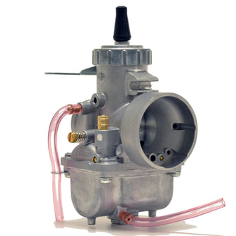
The genuine Mikuni public release (a.k.a. aftermarket carbs) are designed to fit a wide variety of applications. These carbs often closely resemble OEM carbs, but usually have some differences - like choke, idle screw or mixture screw location. These carbs can often be substituted for OEM carbs as long as the jetting or other differences are accounted for to work on a particular model. The very popular, round slide, VM aftermarket series carbs can be found on vintage street bikes, racing motorcycles, snowmobiles as well as experimental aircraft and farm equipment.
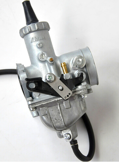 A counterfeit Mikuni
I mentioned a third group of Mikuni carbs - but they're not really Mikuni at all. They are cheap, imitation, Mikuni knockoffs. These fake Mikunis are being built and distributed around the world. Most are manufactured in China, some are made in India and I'm sure, there are others being made elsewhere. You usually see these carbs on eBay in the $25-65 range. They are poorly manufactured with cheap materials and don't work well - if at all. Genuine Mikuni parts will not fit on these carbs even though the look very similar. My suggestion is to stay away from these carbs.
If you're looking to replace your OEM carb with a genuine Mikuni carb, you'll find Niche Cycle Supply and MAP Cycle will have what you need. MAP Cycle has been providing vintage, British bike enthusiasts with parts (including Mikuni carb kits) for over 45 years, while Niche Cycle provides parts for Japanese, German, Italian, Spanish as well as US brands. They also have parts for PWCs, ATVs and snowmobiles. They're one of the largest Mikuni dealers anywhere and their prices are very reasonable. They also have a great selection of parts, fast shipping and superb customer service. They also offer a wide assortment of kits and pre-jetted carbs for many applications.
If you're looking to replace your OEM carb with a genuine Mikuni carb, you'll find Niche Cycle Supply and MAP Cycle will have what you need. MAP Cycle has been providing vintage, British bike enthusiasts with parts (including Mikuni carb kits) for over 45 years, while Niche Cycle provides parts for Japanese, German, Italian, Spanish as well as US brands. They also have parts for PWCs, ATVs and snowmobiles. They're one of the largest Mikuni dealers anywhere and their prices are very reasonable. They also have a great selection of parts, fast shipping and superb customer service. They also offer a wide assortment of kits and pre-jetted carbs for many applications.
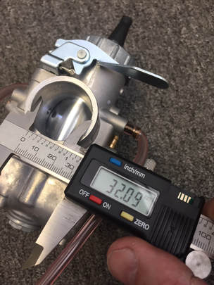
Size does matter, but bigger isn't necessarily better!
Before you loosen the first hose clamp to remove those old carbs, there are a few things you need to figure out. First, you need to give those carburetors a chance to work right by determining the correct carb size you'll need. If you put on too big or too small a carb, your bike is going to run like kaka - if at all.
Let’s say your bike is basically stock. You pull off the old carb and determine that the venturi size is 28mm on that carburetor (this can be done by measuring with a caliper). Let’s also say you haven’t made any radical changes to the bore size, head, valves, cams, air cleaner or exhaust. Then, in most cases, it would be wise to take advantage of the knowledgeable engineers who designed this bike and replace that carb with a 28mm aftermarket carb of similar specifications. If you decide you know more than the engineers, and you stick on a 30 or 32mm carburetor under the misguided precept that “bigger is better,” you’ll quickly find you're bringing in more of a fuel/air mixture than your valves, cams and exhaust can handle. You can try to choke down the carb with smaller jetting but that won't make it right. You're opening yourself up to a mechanical nightmare.
On the other hand, if you added a big bore kit, a nice street cam, and maybe less restrictive aftermarket air cleaners and exhaust, you’re probably going to want to step up in size a bit - maybe to a 30mm carburetor. If you've had some professional head work done, adding larger valves and increased porting, then maybe a 32mm would work. I'm sure you get the picture - don't go bigger unless your bike has been modified to accept the increased fuel/air mix.
Let's say you decided to go ahead and order a carb kit. While your carbs are being shipped, I suggest you do a little pre-installation prep work. First, you'll want to make sure your motorcycle is maintained properly and ready for the new carbs, otherwise, your bike will still run like kaka - even with brand new carbs. If you valves aren't opening or closing properly or if your spark plugs aren't firing at the right time, new carbs won't make any difference at all. So before you you even think about putting on those great-looking new carbs, get out the tools and do a little maintenance. This is definitely not as exciting as bolting on a new kit, but it’s an absolutely necessity if you want this project to go smoothly. Experienced mechanics know that if you go at this project methodically and do what needs to be done, it will go a lot smoother and a lot quicker in the long run. Even if you feel your bike is running great, you’ll want to start this project by checking your bike’s valve clearances and timing. It’s a good idea to have a shop manual handy so you can get the correct specs you’ll need to make adjustments (rather than relying on information provided by some bonehead in a user group with little actual experience).
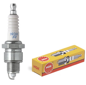
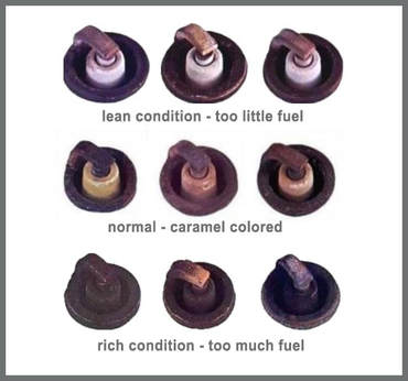
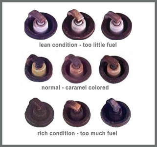
One of the things you're going to require to properly jet the bike is a box of new spark plugs. The spark plugs are the canary in the coal mine. They are the first indicator that things are going right or wrong with your engine. If all is well, the ceramic tip on plugs should turn from white (when new) to are a caramel color (after a few minutes of running). If you inspect the plugs and the tip is dark gray, black or worse, sooty, then you have a rich condition, or too much fuel in the fuel/air mixture being provided by the carburetor. If it's a lean condition, the plugs will tend towards a bright white color. As you go though the jetting and tuning process, be sure to compare your plugs to the chart we’ve provided below.
Not only will a spark plug tip color provide you a good indication of how well your bike is currently set up, it will also give you a baseline for comparison after changes have been made. More on that later in the tuning section.
Not only will a spark plug tip color provide you a good indication of how well your bike is currently set up, it will also give you a baseline for comparison after changes have been made. More on that later in the tuning section.
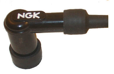
While on the subject of spark plugs, be sure to check out your high tension leads. That's the spark plug wires (originating from the coil) and and the spark plug cap. Make sure the wires are not old or cracked in any place and make sure there is no cracking on the cap or a missing boot around the base of the cap. Misfiring or jumping sparks can cause a real problem. Spark plug wires should be pliable (easily bent without cracking). If there are cracks in the wires on on the cap, you will have to replace them. If you don't you're going to have arching and a restricted spark. If you’re in a place without bright light, you should be able to see a bright blue spark coming from the plug’s electrode when it’s grounded against the head (while cranking the bike). And hopefully, there will be no other sparks emitting from either the lead wire or from cracks in the cap. If you see sparks coming from anything other than the spark plug, you need to replace the wires or caps. This needs to be done before you put on the new carbs.
You might be tempted to skip these checks, but it’s universally recommended in almost every good book or article on carburation and tuning. These authors consider this a must-do procedure before you make any attempt to adjust your carburetors. It's just as critical, if not more, when converting to different carburetors. One you know the the timing and valves are correct, if you have any problems, you can narrow it down to the carburation, rather than looking all over the place for a cause. If you’ve had issues with the way your bike is running (down on power, etc.), you’re going to want to do a compression check to make sure your engine is meeting minimal factory specifications.
When you start the project, have some additional fresh plugs standing by as well, in case your adjustments are off and you foul your plugs (you need them for jetting anyway). Another suggestion, if you’re installing new, expensive new carbs, you might as well do the job right. Be sure to replace the manifold gasket, fuel lines, hose clamps, fuel filter, control cables and air cleaner. If you're working on an old two stroke, clean out the exhaust system. A build up of oil in the exhaust can restrict the flow of exhaust gasses. A problem with anyone of these items can marginalize performance and create an unnecessary problems during the tuning process.
Understanding the Mikuni Carb
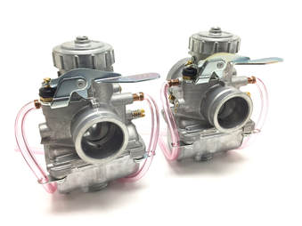 Mikuni VM "round slide" carbs
The very idea of installing and tuning a new motorcycle carburetor may at first appear daunting to anyone but an expert, but if you understand the basics of how a these devices work, you’ll find it’s a lot easier than expected. As you probably already know, there are many types of carburetors, but for simplicity’s sake, this article will focus primarily on the Mikuni VM and TM series. That being said, many of the concepts presented here can be applied to most motorcycle carburetors.
A carburetor’s job is simple: mix fuel and air, and then deliver this explosive mixture to the engine’s cylinder where it’s compressed, ignited and finally, exhausted. The trick is to adjust that mixture (ratio) almost instantly on the fly and deliver it consistently to the engine when needed. Mikuni carburetors do a nice job of meeting these requirements and they also provide good performance, high efficiency and in most cases, decent fuel economy.
 Mikunis were first noticed on 1960s-era Japanese motorcycles.
A Little History
Mikuni was founded in Japan in the early 1920s. During the 1930's they were reproducing carburetors under license by Amal. The new Mikuni round-slide carburetor started hitting US and European shores in the mid 1960’s mounted on two-stroke, Japanese motorcycles. They quickly developed a reputation for reliability. Racing tuners and mechanics loved them for their performance and ease of maintenance. They’ve became so popular they can now be found on a wide variety of applications, including ATV’s, snowmobiles, boats, agricultural machinery, go-karts and all kinds of gas-powered equipment like generators, welders and compressors. They are, without a doubt, the most popular motorcycle carburetors available. They come in a variety of sizes and are highly adjustable, which makes them ideal for customized or racing applications.
Basic Carburetor Theory (highly simplified!)
I'd bet most professional mechanics can't explain Bernoulli’s principle, Newton’s third law or have an understanding of fluid dynamics - but most understand the basics of how a carb works, if not the science of it. While a thorough knowledge of these theories no doubt helped engineers develop today’s dependable and efficient carburetors, you really don’t need much more than a basic understanding of how they work to install and tune a carb.
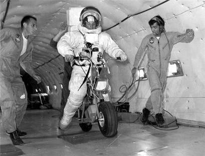
A great place to start with the understanding that all carburetors require atmospheric pressure to function. That's why your vintage Bonneville wouldn't start if it were parked outside the International Space Station - even with a new MAP Mikuni kit installed! You may not realize it, but as long as you’re on this planet, you receiving constant atmospheric pressure applied to your body - almost 15 pounds per square inch at sea level. That's typically referred to as one atmosphere in the diving community. Take a dive into the ocean and drop below 30-feet and things start to change. and scuba divers know that you can increase the atmospheric pressure on your body by descending just below one meter or 33 feet. By the time you’ve dropped to 66 feet, you’ve doubled that pressure to nearly 30 pounds. If you’re breathing though a regulator, you’ll find that pressure makes it much harder to breath.
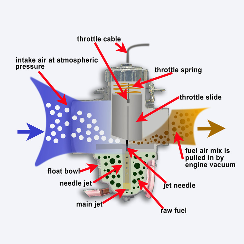
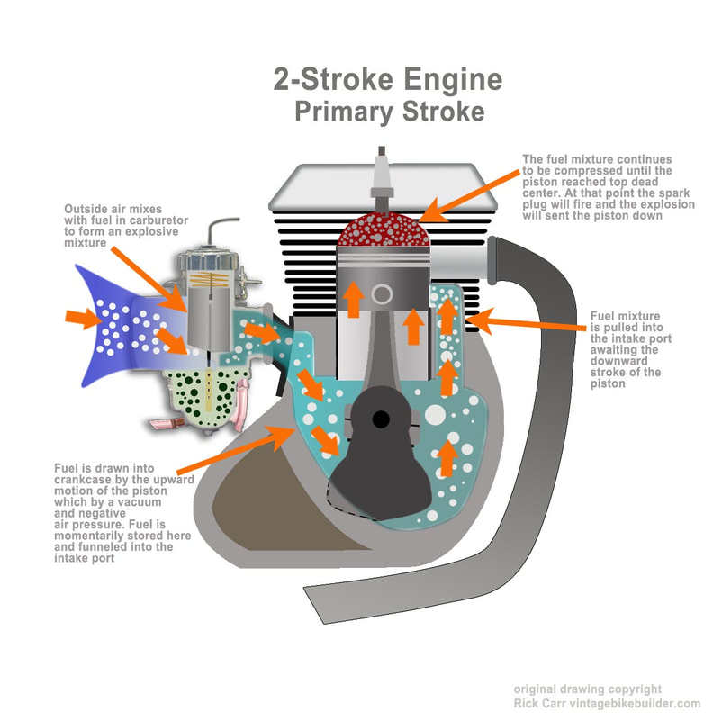
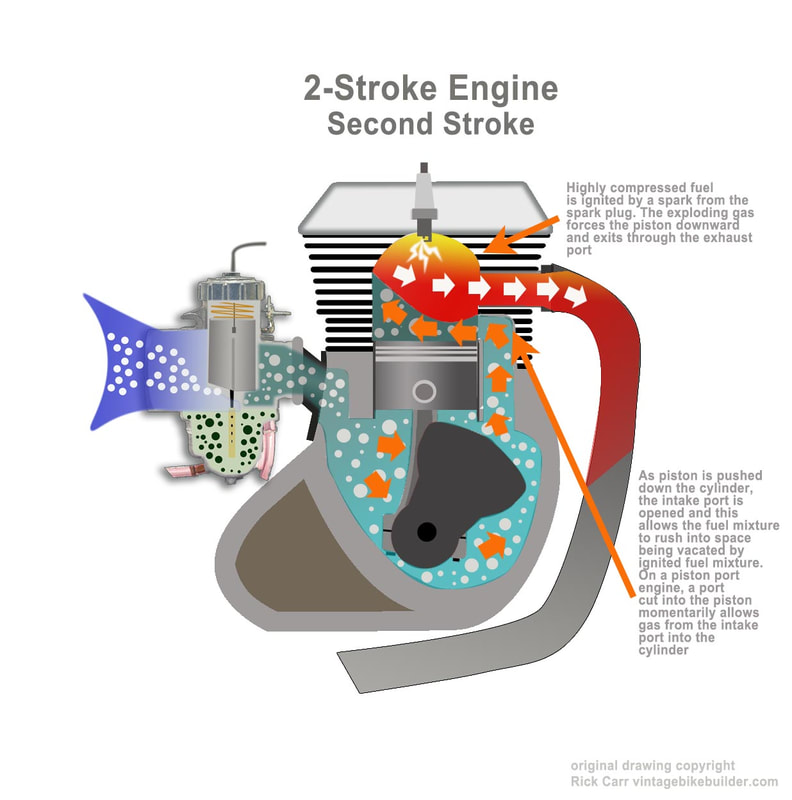
That same atmospheric pressure pushing on a scuba diver’s lungs also allows carburetors to function. Areas of high pressure naturally displace areas of low pressure. When the kick starter on a two-stroke engine is pushed down the piston goes up and an area of low pressure is instantly created in the crankcase. On a four-cycle engine that same thing happens with the piston is descending through its intake stroke. If you were to take a virtual snapshot of this moment in time, you’d see that pressure on the outside of the carburetor (air cleaner side) is high and the pressure inside the crankcase (on the two-stroke engine) or in the cylinder (4-cycle engine) is lower (see illustration #1). This low pressure is created by a vacuum caused by the ascending piston. Because of this difference in pressure, the air instantly rushes though the carburetor until that pressure is equalized. On a running engine, that air flow is continuous and can be manipulated in the carburetor to provide a higher or lower volume of that critical fuel/air mixture. This is how a carburetor governs the speed of an engine.
You can go one step further into carburetor theory if you like. Inside every carburetor is a venturi. A venturi is a generally described as a tube with a narrow section placed somewhere between two wider ends. This narrowing creates low pressure (and suction). Swiss mathematician and physicist, Daniel Bernoulli, discovered this way back in the 1700’s. He discovered that was a direct correlation between the speed of fluid and the pressure that is exerted on it. He observed that as fluid speeds up in the narrow section of the venturi, the pressure is lowered. Conversely as it slows down pressure is increased. He went to to prove this theory with gas as well as fluids. The clever designers of the Mikuni carburetors use the venturi to their advantage to efficiently draw air and fuel into the body of the carburetor. Next UP: The primary circuits of the carburetor (you’ll want to read this).
Mikuni’s Metering Systems
If you're working on them, then it’s absolutely essential to have a clear understanding of the major circuits (or metering devices) of the Mikuni carburetor. The Mikuni VM has four major circuits which effect fuel delivery to the engine. Each of these systems work in concert other circuits to provide optimal fuel delivery.
If you're working on them, then it’s absolutely essential to have a clear understanding of the major circuits (or metering devices) of the Mikuni carburetor. The Mikuni VM has four major circuits which effect fuel delivery to the engine. Each of these systems work in concert other circuits to provide optimal fuel delivery.
An easy way to visualize the carb's effect on the powerband
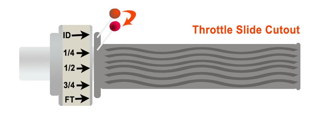
Using sewing pins (I like the ones with the big read head) or a white wax pencil, divide your throttle into four equal segments by placing a pin or mark onto the rubber grip (see illustration below - we'll choose pins for this one). On the housing place a piece of tape and draw an arrow pointing to the pin (or mark) on the bottom of the grip. This position is representative of the throttle being closed (see illustration below).
If you have an issue with jetting, you can use this method to determine where in the power-band the problem exists. Keep in mind, you may have more than one issue and these issues may effect more than one area of the carb. But this exercise will help you narrow down the cause of the problem.
We will also use this exercise to identify what component of the carburetor effects any given segment of the power-band. We'll start with the pilot system which regulates fuel when the throttle is completely closed and the engine is at idle.
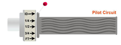 The pilot circuit provides fuel to the carburetor primarily at idle (ID)
The Pilot System
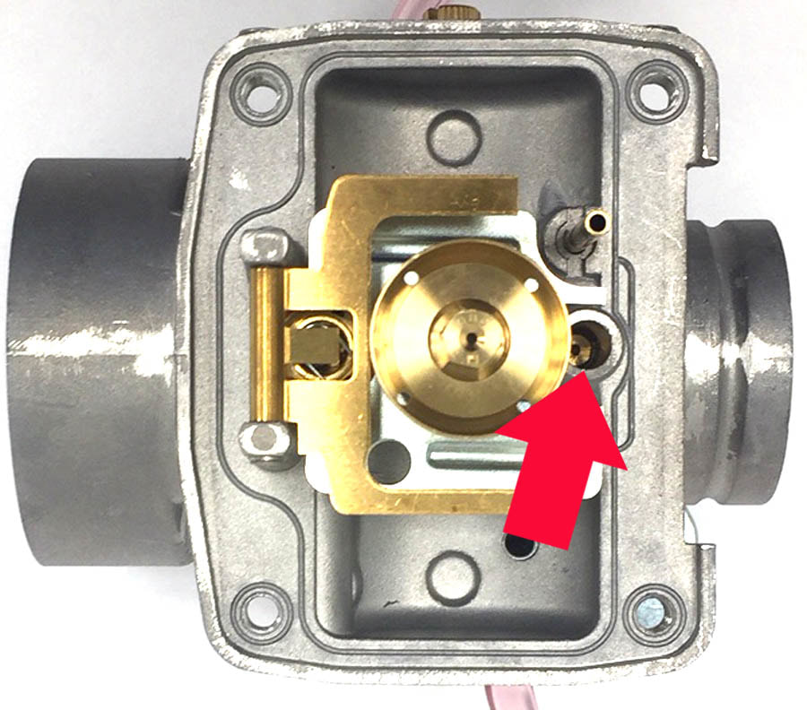
This system works at or just above engine idle (see diagram). Only a very small amount of vacuum can be created by the engine when it is at idle speed. The pilot system is placed nearest the intake manifold (where there is the most suction) because of the limited velocity of air (vacuum) moving through the carb at idle speed. Limited velocity equals limited suction – that’s why the fuel for this circuit needs to be easily drawn from the pilot circuit. The pilot circuit is controlled by means of a pilot outlet and a bypass. At idle, fuel metered by the pilot jet is mixed with air and broken into fine particles of fuel vapor. This is adjusted by the air or fuel screw, which is also sometimes known as the pilot screw. When the throttle is opened slightly, the bypass draws in more fuel in to immediately compensate for the increased airflow. The pilot jet works in coordination with the fuel/air mixture screw also often referred to as the pilot screw. Like the pilot jet, this screw has little to no effect on the fuel/air mixture above idle speeds.
This system works at or just above engine idle (see diagram). Only a very small amount of vacuum can be created by the engine when it is at idle speed. The pilot system is placed nearest the intake manifold (where there is the most suction) because of the limited velocity of air (vacuum) moving through the carb at idle speed. Limited velocity equals limited suction – that’s why the fuel for this circuit needs to be easily drawn from the pilot circuit. The pilot circuit is controlled by means of a pilot outlet and a bypass. At idle, fuel metered by the pilot jet is mixed with air and broken into fine particles of fuel vapor. This is adjusted by the air or fuel screw, which is also sometimes known as the pilot screw. When the throttle is opened slightly, the bypass draws in more fuel in to immediately compensate for the increased airflow. The pilot jet works in coordination with the fuel/air mixture screw also often referred to as the pilot screw. Like the pilot jet, this screw has little to no effect on the fuel/air mixture above idle speeds.
The Throttle Slide or Throttle Valve
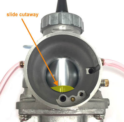
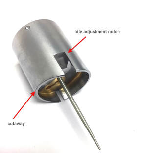
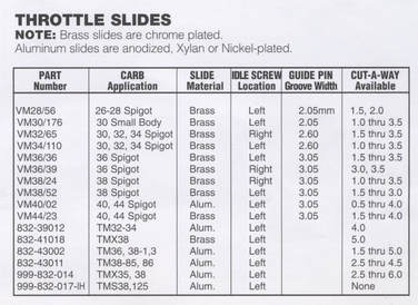
If you look at most round or flat slide motorcycle carburetors, you’ll see a small arched cutout on the intake side of the carburetor. This is the throttle slide cutaway. The cutaway begins to regulate the fuel/air mixture the moment the throttle is cracked open. As airflow increases through the venturi, so will vacuum. The increased vacuum begins to pull fuel up through the needle jet (see below) rather than draw fuel from through the pilot circuit. At that point, the pilot circuit cannot provide enough fuel to match the increased air flow. Keep in mind that each circuit works with the circuit(s) before it. The transition from the bulk of the fuel now being supplied by the needle jet, rather than the pilot, should be a seamless, and it will be if you have the correct pilot, slide cutaway and needle jet combination.
The carburetor can be adjusted for this part of the power-band by installing a throttle slide with a larger or smaller cutaway. The larger opening allows more air into the fuel/air mixture which makes it leaner. A smaller cutaway does the opposite, making the mixture richer. Of course the needle jet can be changed as well and there's more on that in the next segment.
The slide cutaway has an effect on airflow during early acceleration through the first part of the mid-range. After that, the slide is pulled up higher in mixing chamber and air flow is increased to the point where the slide cutaway is no longer effective.
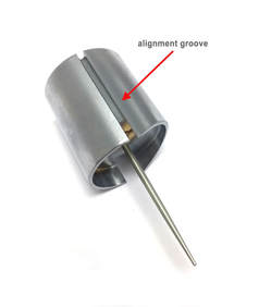
When looking at the throttle slide of a VM Mikuni, you'll notice there are two different notches cut into each side of the slide. One is skinny and runs the full length of the slide, the other is thick and runs part way up. The skinny notch is for keeping proper alignment of the slide - essentially to keep the slide from rotating to the left or right and to keep the cutaway centered in the intake. The shorter, fatter notch on the opposite side is where the idle adjustment screw makes contact. As the screw is rotated inward, it pushes on the slide lifting it and raising the idle speed.
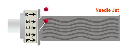 Changing the needle jet would effect the lower to middle portion of the mid-range
The Needle Jet and Jet Needle
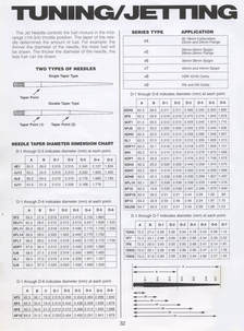
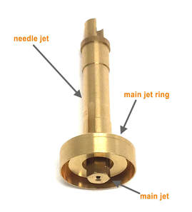
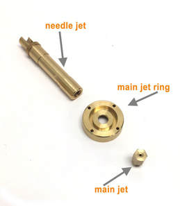
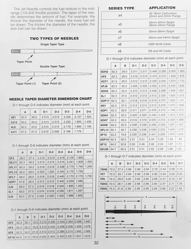
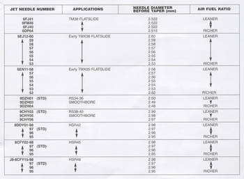
The needle jet and jet needle regulate fuel delivery throughout the mid-range. As mentioned above, the needle jet takes over most of the fuel delivery from the pilot circuit as the throttle is opened. Needle jets are available in an assortment of sizes for most of the Mikuni round-slide and flat-slide carburetors. The Mikuni jetting chart below matches different series needle jets with various model carburetors.
The needle jet and jet needle regulate fuel delivery throughout the mid-range. As mentioned above, the needle jet takes over most of the fuel delivery from the pilot circuit as the throttle is opened. Needle jets are available in an assortment of sizes for most of the Mikuni round-slide and flat-slide carburetors. The Mikuni jetting chart below matches different series needle jets with various model carburetors.
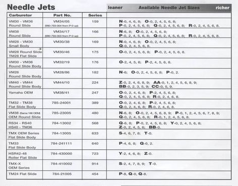 Needle jet chart from the Mikuni catalog
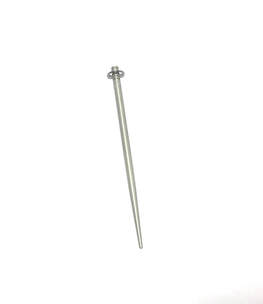
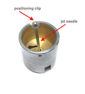
The needle jet works in conjunction with the jet needle. The jet needle is a tapered cylinder that looks a lot like a sewing needle. It is suspended from the bottom of the throttle slide and held in place by the slide return spring and spring plate.
A positioning clip at the top of the needle suspends the needle from the bottom of the slide. There are typically 5 clip positions on the Mikuni’s VM needle. This clip determines how deep the needle penetrates through the needle jet. This clip can be easily adjusted up or down. Raising the clip drops the needle and limits how much fuel can enter the venturi. This makes the mixture leaner. Conversely, dropping the clip to a lower notch will raise the needle inside the needle jet. This allows more fuel in and makes the mixture richer.
A positioning clip at the top of the needle suspends the needle from the bottom of the slide. There are typically 5 clip positions on the Mikuni’s VM needle. This clip determines how deep the needle penetrates through the needle jet. This clip can be easily adjusted up or down. Raising the clip drops the needle and limits how much fuel can enter the venturi. This makes the mixture leaner. Conversely, dropping the clip to a lower notch will raise the needle inside the needle jet. This allows more fuel in and makes the mixture richer.
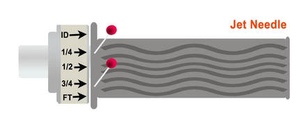 The position and size of the jet needle has an effect on the entire midrange
Jet needles are avail in both single taper and double taper. This allows for precise tuning of the widest and must used part of the powerband.
There are a wide variety of needle sizes and shapes available. The Mikuni chart below provide a comprehensive listing of the needle jets available for their round-slide carburetors.
It's important to note that the jet needle has and effect on the widest part of the powerband. This can be seen in the image to the right.
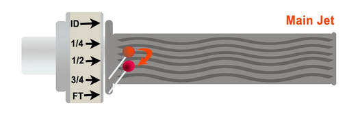 The main jet meters fuel use for the upper end of the power-band
The Main Jet
When you grab a handful of throttle and rev the engine to the top 25-percent of the power band there is a significantly greater demand for fuel. In this power range, Mikuni carbs pull fuel from from the high speed circuit.
As the throttle slide is pulled up almost all the way, the jet needle protruding from the bottom of the slide clears the needle jet and opens up a direct passage from the float bowl, through the main jet, directly into the mixing chamber. On round-slide carbs, this is the most direct route for the fuel, but it requires a lot of vacuum to work. As it is with the pilot jet, it's important that the right ratio of fuel is being delivered to the engine. The size of the jet determines how much or how little fuel reaches the mixing chamber. Mikuni offers a wide variety of main jet sizes.
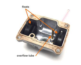
Additional Components
The Float System
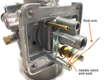
The float and float bowl work together to provide raw fuel though out the entire range of operation. The float bowl is a container that holds fuel. The float(s) purpose is to maintain a constant level of fuel in the float bowl. Fuel flows from the bike’s fuel tank, past the petcock, through the fuel line into a fitting on the side of the carb. From there it takes a couple of 90-degree turns and flows past the needle valve and seat (not to be confused with the jet needle or needle jet). As the fuel rises, the float(s) become buoyant and are pushed upwards along with the fuel. At a specific point, the floats will push the float arm up which has a small tab that rests on the float needle.As the fuel continues to rise that tab will push the needle into the seat, closing off the flow of fuel (see illustration). The float system is important because it affects all other fuel delivery systems on the carb. Tab on the float arm comes set at a particular height from the factory, but the float arm is fragile and sometimes the tab needs adjustment to keep too much or too little fuel from entering the float bowl. If there is too much fuel, the carb may overflow or it may flood the needle jet causing a rich condition. Too little fuel may cause the bike to run lean or not at all.
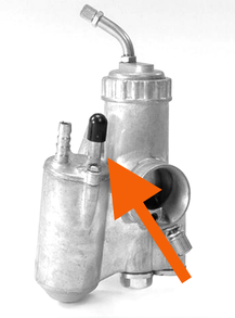 This float tickler for enriching mixture functions as a crude choke
The Starter Circuit
In order to create a combustible mixture for the cylinder to ignite, some of the fuel has to evaporate and turn into a vapor. When that fuel vapor mixes with the air (in the right percentage), it can be easily ignited in the cylinder by a spark from the spark plug. If the fuel mixture isn't correct, the engine won't start.
If the engine has been recently run, the heat from the engine allows fuel in the carb to vaporize quickly. When the engine is warm you don't need a choke. But, if the engine is cold, the fuel won't easily vaporize and it has to be enriched with more fuel than normal - that is the purpose of the choke circuit on the Mikuni round slide carburetor. There are several way to accomplish this. Amal carbs (most often seen on bikes built in the UK), Bings (frequently seen on German and northern European motorcycles) and Delorto (Italian and Spanish bikes) have in the past used a primer or tickler device to put more raw fuel into the carb. This is essentially a device that bypasses the float system and allows an excess of fuel to flood into the float bowl enriching the fuel/air mixture - this is called priming the carb. This flooding of the float bowl works when the engine is cold, but it would keep it from running if it was hot.
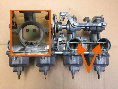 The arrows show the butterfly choke open and the inset shows the choke closed
Some carburetors utilize a simple butterfly valve that restricts air flow coming into the mixing chamber of the carb. By restricting air intake, the fuel side of the mixture is increased, thus enriching the mixture. These butterfly valves are frequently seen on Kenhin CV carbs used throughout the 1970s and 80s by Honda. You'll also find them on vintage Harleys and Indians and almost every car and lawnmower made prior to 1980. This device is simple, but it does not provide an optimal, precise, mixture for starting an engine.
Of course, the simplest choke is the Redneck Choke. It's a bit of gas poured onto a rag and held over the opening of the carb. But, this exercise could be fraught with potential bad outcomes. If the backfires, you could easily catch your bike on fire , or worse yet, yourself. It is not recommended. I'm sure my attorney would advise me to tell my readers to NEVER, EVER, UNDER ANY CIRCUMSTANCES DO TRY THIS. Consider yourself told!
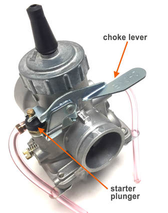
None of the above methods is as effective as Mikuni's dedicated choke circuit. With Mikuni's enrichment circuit, fuel is delivered from the starter jet which is near the bottom of the float bowl. As this fuel is drawn into the emulsion tube, it is broken into tiny, microscopic-sized particles. These particles flow into the into the choke plunger area where it mixes with air in a precise ratio. When the choke lever is depressed (or cable pulled), a plunger moves up allowing this fuel vapor mixture to pass into a fuel discharge passage where it is delivered to the engine. Since vacuum is necessary to draw the fuel up, it is important that the throttle remain closed when using the starting system to start the engine. If you open the throttle on a Mikuni when you choke it, it will defeat the choke every time.
The Air/Fuel Mixture
Why is a precise air/fuel mixture ratio important? Well, if the ratio is too far off, the engine simply won't run. Before the days when fuel injection was common in cars, you'd often witness the result of a someone over-enthusiastically pumping their gas pedal. First there would be the tale-tale smell of raw gas the air, and maybe a small puddle of it under the engine. Then you'd hear the car turning over...waawaawaawaawaawaa, waawaawaawaawaawaa, waawaawaawaawaawaa, without starting. Then someone would always say, "It's flooded. Let it sit a bit." That mixture would be almost all gas and no air. Running out of gas would be on the other end of the spectrum with no fuel getting to the carb at all.
|
But even small differences in the fuel mixture can make a huge difference in engine performance. A fuel mixture that is too lean will sometimes make your bike feel like its performing better, but it can also overheat the engine and do permanent damage very quickly. A lot of race teams run their bikes with a lean mixture, but those engines only need to last one race. A mixture that is too rich will let the engine run cooler, but it will also cut way back on performance. Without expensive, automotive diagnostic measuring equipment, the best way for the layman to tell if their mixture is spot-on is by the color of a new spark plug insulator after running the bike under certain conditions for a few minutes.
Take a look at the color of the ceramic insulators in the photo to the photo below. The spark plugs with bright white insulators are indicating a lean condition, or not enough fuel. The dark or sooty plugs are indicating too much fuel in the mix. The plugs in the middle are a nice caramel color. They indicate the correct fuel mixture. Ideally, you want your plugs to be this color. |
What is the perfect fuel/air mixture? For those intellectually curious individuals, engineers have found the ideal air/fuel ratio is approximately 14.7 grams of air to 1 gram of fuel (give or take a fraction of a gram). Unfortunately, this ideal ration can only be achieved when the engine is running and only for a short period of time. This is because at slow speeds the fuel can vaporize effectively and when the engine is running at higher speeds more fuel is needed in the ideal mixture. So, for practical purposes, a "real-world" operational air/fuel ratio is usually a bit richer. |
On most engines, a properly jetted Mikuni carburetor will typically deliver somewhere between 12-15 grams of air for every 1 gram of fuel. This "ideal" mixture will provide maximum efficiency and performance.
But, within that ideal range, there are many variables that must be taken into account. It begins with type of engine and how it is cooled. It is known that air-cooled engines do not operate as efficiently as water-cooled engines. Therefore, they require a richer mixture of between 10-12 grams of air for every one gram of fuel to help keep the engine cool. While a water cooled engine can get by on a leaner mix, say 14 grams of air for every gram of fuel.
If you don't have a lot of diagnostic equipment attached to your bike, the tried and true method of determining the quality of the fuel mix is by examining the electrode of a fresh spark plug during a test of the carb. We'll get more into that as we talk about tuning. But if you look at the chart above, you can see a line of bright white plugs. They may look nice and clean, but if your plugs look like that, you may be on the verge of ruining your engine. Bright white electrodes are an indicator of a lean condition. That means the mixture ratio going into your engine has too little air and not enough fuel. To get more fuel into the mix, you'll would typically install larger jets, raise the jet needle (by dropping the clip) or install a throttle slide with a smaller cut away. Any individual combination of those actions would bring more fuel into the mix. But you probably wouldn't need to make all of those changes. Again, more about that in the jetting section.
Conversely, if the inspection of your spark plug electrodes reveal a rich condition, that means, your carb is delivering too much fuel to that all important fuel/air mix. If that is the case, your plugs will look like those on the bottom line of the chart- dark gray, black or sooty. You'll want to reduce your jet size, drop your needle or use a larger cutout on the throttle slide. But again, probably not all at the same time. We explore more about this in the tuning section.
Getting started with Tuning
|
Doing the job right
Even expert mechanics, who install carburetors on a daily basis, make silly mistakes. How likely is it then for someone who does it occasionally, or has never done it, to screw up? For most of us, purchasing a carburetor kit is a fairly expensive investment. So it pays to do a little planning and preparation BEFORE you attempt to rebuild a carb or begin installing a carb kit. Even if you don't like instructions, you should protect your investment by thoroughly reading the notes and instructions provided for you. Don't take shortcuts. Pay special attention to the tips below. These instructions have come about from years of other folk’s mistakes and misery. Let their errors pave the way for your success! |
Safety Note: Handle all fuels with extreme care in a well-ventilated area. Gasoline is highly flammable and extremely dangerous. Drain fuel using great care. Do not allow any smoking or electrical sparks nearby while transferring fuel. Do not leave fuel in open containers unattended. Do not allow children to handle fuel. |
Tips for a successful carb installation or rebuild
|
Notes on fuel: Because of possible fuel contamination, we always recommend you drain any existing fuel from your fuel tank. One of the main causes of carburetor failure is contaminants in the fuel. You don’t want to mess up your new carb with dirty gas. If you question whether or not your fuel is dirty, empty about a cupful from the petcock into perfectly clean, glass container. Place the container on a level surface in a well-ventilated area and let it sit for 30 minutes. If after 30 minutes, you can see sediment on the bottom of the container, you need to drain your fuel and add a new fuel filter. If you see what looks like a line in the fuel with two different colors, that means you have water contamination. In either case, you need to drain your tank and get new fuel. However, just draining your tank provides no guarantee that your gas tank will then be completely clean. To have a clean tank, you'll need to empty all the fuel, wash out the tank with Dawn detergent and water and then blow dry the tank with compressed air or clean, warm, blown air (not sucked) from a shop vacuum (vacuums must have blower feature to do this). If it's a metal tank, it can rust quickly. To prevent that, I usually pour in a couple ounces of cheap crankcase oil (any weight is fine) or two-stroke motor oil, slosh it over every inch of the tank and then drain any remaining oil before reinstalling the tank and filling it with fuel. Make sure the tank is absolutely, completely, BONE DRY before adding any fuel. DO NOT USE ANYTHING WITH OPEN FLAME TO DRY THE TANK!!! If your tank is rusted, you'll need to look at using a fuel tank sealer from a manufacturer like POR, Kreem or Red-Kote. POR has a really good system and the motorcycle kit comes with everything you need. The Best Way to Transfer Fuel: In a well-ventilated area, with the petcock in the off position, attach about 2 feet of hose to the petcock (the length of the tubing may vary depending on size of the container being used). Place the other end into a container designed and approved to hold fuel. Make sure there is enough room in the container for the remaining fuel in the tank before transferring the fuel. If the fuel capacity is two gallons on your bike, then use a larger container - like 2.5 gallons. Turn the petcock on and stay with the container until the tank is empty. Seal the container. Check with your city or county waste service to find out how to dispose of the old gas properly. Do not smoke anywhere near an open container. Avoid any sparks while transferring fuel. |
- Eliminate potential air leaks - The best way to avoid air leaks is to install new manifold gaskets to perfectly clean manifold surfaces. Remember, air leaks are the enemy of a successful carb installation. It seems whenever old paper gaskets are removed, they leave pieces of material stuck to manifold surface. Sometimes it’s a pain to remove, but you have to do a good job. Use a razor blade (pressed flat and parallel to the surface) to lift as much of the old gasket material as possible. Be careful not to gouge the aluminum surface of the manifold. DO NOT USE A CHISEL OR SCREWDRIVER TO SCRAPE THE MANIFOLD SURFACE! Use a scrubbing pad with some lacquer thinner or acetone to clean the surface and make sure all remnants of the old gasket are removed. Make sure you have blocked off the manifold so no gasket remnant drops inside. You shouldn't need any kind of gasket sealer. Manufactures don’t use it with paper gaskets you shouldn’t need to either. Make sure the manifold nuts (or bolts) are tightened equally, in stages. Don’t crank down one side and then the other. Rather, snug up one side and move to the other, going back and forth until fully tightened. DO NOT OVERTIGHTEN. You should always use a wrench or a small 1/4” drive ratchet and socket to tighten the manifolds down. Never use an air impact or a larger 3/8 or ½” drive. The last thing you want to do is break off a stud or crack a manifold. If you're using a rubber flange adapter or straight rubber adapter, make sure the carb is fully seated within the adapter. Mikuni carbs have a groove cut in the spigot that fits into a raised rubber channel in the Mikuni flange and straight adapters. When a Mikuni carb is properly seated in a Mikuni adapter, you can feel it pop in and it will often be accompanied with a clicking sound. If you pull back gently on the carb, it will not pop out, even when if it's not clamped. Speaking of clamps, be sure to use the correct size clamps (usually provided with kits) and make sure they are tightened to the point where the carburetor will not rotate if you try to twist it. Make sure the air box boot or pod filter is secured to the intake bell of the carburetor and secured with the proper hose clamp. It’s imperative there are NO air leaks.
- Set up cables correctly - Your throttle cable(s) must be the correct length, correctly adjusted without slack and must be routed properly. That way, when you turn the handlebars it won't pull on the cable and raise the throttle slide (increasing RPMs). You also have to make sure your throttle slide opens and closes fully without any hesitation or drag on the slide. It's not fun dealing with a wide-open, stuck throttle while you whizzing down the street or through the woods. If you're using a choke cable, the same rules apply. If your choke is not opening or closing fully, you can will never get the bike tuned correctly. If you have multiple carburetors, make sure they are synced and moving at the exact same time (more about that later). Also, be sure to check the play in your throttle cable. Ideally, there should be minimal play, about 1mm at the throttle.
- Eliminate potential for fuel leaks -. Be sure you replace old hose clamps with new ones. This will save you aggravation in the long run. Fuel leaks can be just as problematic as air leaks when dealing with carburation. If your new fuel hoses aren't a very tight fit, you'll need some kind of hose clamps to avoid leaks. Make sure your fuel drain lines are routed under the engine and away from hot exhaust. Not only can fuel leaks keep your bike from running right, they are extremely dangerous.
- Use clean fuel - If you try to take a short cut by using old fuel, this one will get you every time! Please see inset above on fuel this will save you a lot of time and aggravation. By the way, this tip is so important, it gets its own section!
- Use clean or new air filters - If you are using the stock air box, be sure the filters are new or like new. Old filters may sometimes look okay, but it only takes a little dirt on the outer layer to restrict air flow, which in turn, can effect proper tuning. On a lot of vintage bikes, you might find it difficult to replace the stock filters. Aftermarket pod filters are a good, inexpensive alternative. Whether you're using the stock air box or pod filters, make sure the air box boot or pod filter is securely fitted around the intake bell. Clamp it using a good, stainless steel hose clamp. For those of you using velocity stacks on the street: sure, they look cool, but they're just not practical. They suck up dirt better than a Dyson sucks cat hair off the floor. And the moment it starts to rain, you'll finally know how well you engine runs with water injection. They also require specialized jetting considerations. But if you insist, just like pod filters and air box boots, velocity stacks need to be secured to the carburetor. There are some carbs, like Amals, with velocity stacks that screw directly onto the intake bell. With these carbs, you might want to use a drop or two of blue Loctite Blue 242.
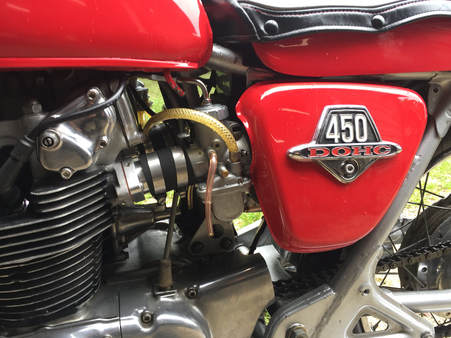 This CB450 has a Niche Cycle - made, dual VM32, Mikuni conversion
Syncing the Carbs
NOTE: If you’re installing a single carburetor, you can jump over to the tuning section. Syncing is a process that applies only to multi-carburetor installations.
Before you can even think about attempting to jet or tune a bike with multiple carbs, they first have to be synced or balanced. This is a static balancing process which differs completely from dynamic balancing balancing. Dynamic balancing is a process that takes place with the engine running and utilizing vacuum gauges. Static balancing should be performed before the bike is ever started.
The goal with static balancing is to ensure that all cylinders are receiving an identical fuel/air mix at the exact same time.
Why do carbs have to be synced?
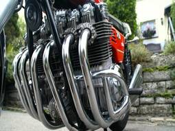 The Benelli Sei has only 3 carbs
A multi-cylinder motorcycle is essentially multiple engines sharing the same crankshaft. If one of those engines isn't running at the exact same speed as the other, performance will suffer greatly. Yes, it will run, but it won't run right. Customers are often shocked at how different the bike runs when the carbs are properly synced. If a carb is out of sync, performance will certainly be diminished, but the bigger issue is the potential damage that can be done to the engine. So, this is not a step you can short cut.
The method demonstrated in this tutorial is for two-cylinder motorcycles (since we sell most of our carbs for that purpose), but similar methods can be applied to three, four or even six cylinder bikes (shout out to you Benelli Sei and CBX owners).
The method demonstrated in this tutorial is for two-cylinder motorcycles (since we sell most of our carbs for that purpose), but similar methods can be applied to three, four or even six cylinder bikes (shout out to you Benelli Sei and CBX owners).
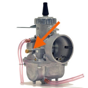 This is the idle screw. Depending on what Mikuni you have, it may be on the right or left side
Syncing Procedure
The objective of this procedure is to get the throttle slides of the carbs moving at the exact same time. Smooth bore carbs with directly connected linkages are done a little differently and we’ll publish a section on that later. This tutorial is primarily for Mikuni round or flat side carburetors that are not linked mechanically.
Mechanical syncing is a three part process: First, we get the throttle cables sorted and adjusted; then we set the idle; and finally, we sync the carbs to each other.
Adjusting throttle cables
It's always a good idea to install new throttle cables when installing new carbs – even if the original cables are still usable. Throttle cables are made up of dozens on tiny wires braided together. As old cables wear, individual wires can break off, and start wearing against the steel inner lining the outer cable. They create friction and make it more difficult to operate the throttle. Once one of the tiny wires break, more will follow. And unfortunately, you will never know for sure unless you cut the end off and pull the inner cable through the outer. You wouldn't want to have to re-sync your carbs again a month or two after installing the carbs, so it one of those "better safe than sorry" things.
Many conversion kits come with new cables, but even factory-built cables require adjustment. Keep in mind that factory-built cables (with the same part number) can also vary in length. It shouldn't happen, but it does. So, if your bike has more than one cable, the first step it so compare the lengths of the cables. If they vary, you'll have to make adjustments to compensate for different sizes.
With the the throttle closed, there should be just the slightest amount of play (about 1mm) in the cable. If you're using dual cables, the cables must have the same amount of free length. That's the amount of inner cable extending beyond the outer sheath. If you're using a cable with a junction (1-into-2, or 1-into-3) make sure that all cable ends are seated in the junction as well as in the twist throttle and carb top. If one or two of the cables are a few millimeters different from the others, don't sweat it. You can use the adjusters to make up the difference in the cable. If it's more than a few millimeters, you might have to solder on a new end fitting to adjust the cable. But, if you do end up having to solder a new end on, don't fret, it's not that big of a deal. You can find out more about that in the cable soldering tutorial.
Setting the Idle Position
If the carbs are already mounted on the bike, try to position yourself where you can look down the bell of the carburetor (the side where the air filter attaches). If you can't look directly down the bell, try using a mirror (of course, if the carbs aren't already mounted, this is easy). While doing this, you’ll notice the base of the throttle slide has an arched cutout at the bottom. We talked about that above, it's called the slide cutout (see The Throttle Slide or Throttle Valve above). The idle adjustment screw on the side of the carb mechanically raises the throttle slide in very small increments. As you turn the screw clockwise, the end of the screw slides further under the skirt of the throttle slide pushing it up and increasing the fuel/air mixture to the engine - increasing the idle speed.
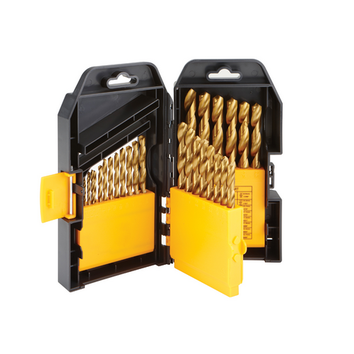
Getting the idle set identically between the carbs is pretty easy - but you need to come up with some kind of inflexible gauge that you can move from one carb to the next to judge the height of the throttle slide. One easy way to do this is to pull out a box of drill bits (aka drill index). If you look at the drill bits in an index, you'll see they increase slightly in size from the smallest to the largest. That makes them perfect for this purpose. Sure, you could use something like a nail or screwdriver, but what if you need a slightly smaller size and don't have a slightly smaller nail or a screwdriver? The cool thing about drill bits is, if one is too small or too big, you just pull out the next size up or down. Make sure you use the smooth shaft of the drill bit and not the cutting edge.
First, make sure your throttle slide is at the very bottom of the slide passage in the carburetor. To do this, you must back off the idle screw until turning it has no effect on the slide. Watch the slide as you turn the screw counterclockwise. You should see the slide drop just a bit. If not, turn the screw in the opposite direction until you see the slide move up, then stop and turn the screw in the opposite direction bringing the slide down a bit. Do this until the slide stops moving. The goal is for the slide to be just barely touching the bottom of the carburetor venturi.
Keep in mind that a poorly adjusted throttle cable can be holding up the side. So once again, check your cable to make sure there's about 1mm play on one of the ends. If you don't have that much play, adjust the throttle cable until you can get that much play. Remember, you can't have the throttle cable adjustment affecting the idle.
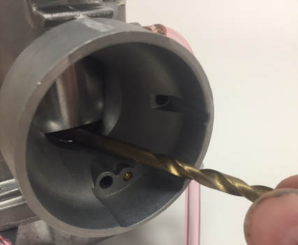
With the slide all the way down, find a drill bit that just barely slides under the throttle slide cutout, without lifting up the slide. You want to use the shank or smooth end of the bit, not the cutting edge. Now, swap out that bit for the next larger size. It should lift the slide up just slightly. If not, grab the next biggest size. One of those bits will typically be enough for the bike to idle. Be sure the drill bit is at a 90-degree angle to the slide - in other words, directly in front of the slide. If you hold it off to one side or the other of the cutout, it will change how much the slide is lifted. Make sure you use the same procedure with the other carb(s). Now, with the drill bit still holding up the slide, turn the idle adjustment screw clockwise (righty-tighty) to raise the slide just enough to release the drill bit. If you make the bit too lose, just loosen the screw a bit (turning counterclockwise) until the slide starts to make contact with the bit again. Then, tighten the idle screw again until it lifts the slide just a hair. This is usually between 1/4 and 1/2 of a turn. With your carb height set, use the same technique to set the idle on the other carb(s).
If you find the bike idles too low, you can either go up to the next size drill bit and repeat the process above, or adjust the idle by turning the idle screw on both carbs the exact same amount (clockwise). For example, if you increase the idle on one carb but turning it exactly 1/4 turn clockwise, then do the same to the other. You can also make small, incremental turns to lower the idle as well.
|
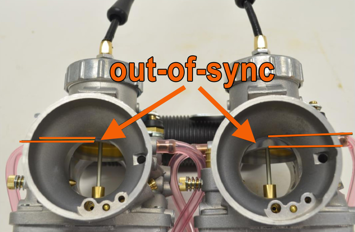
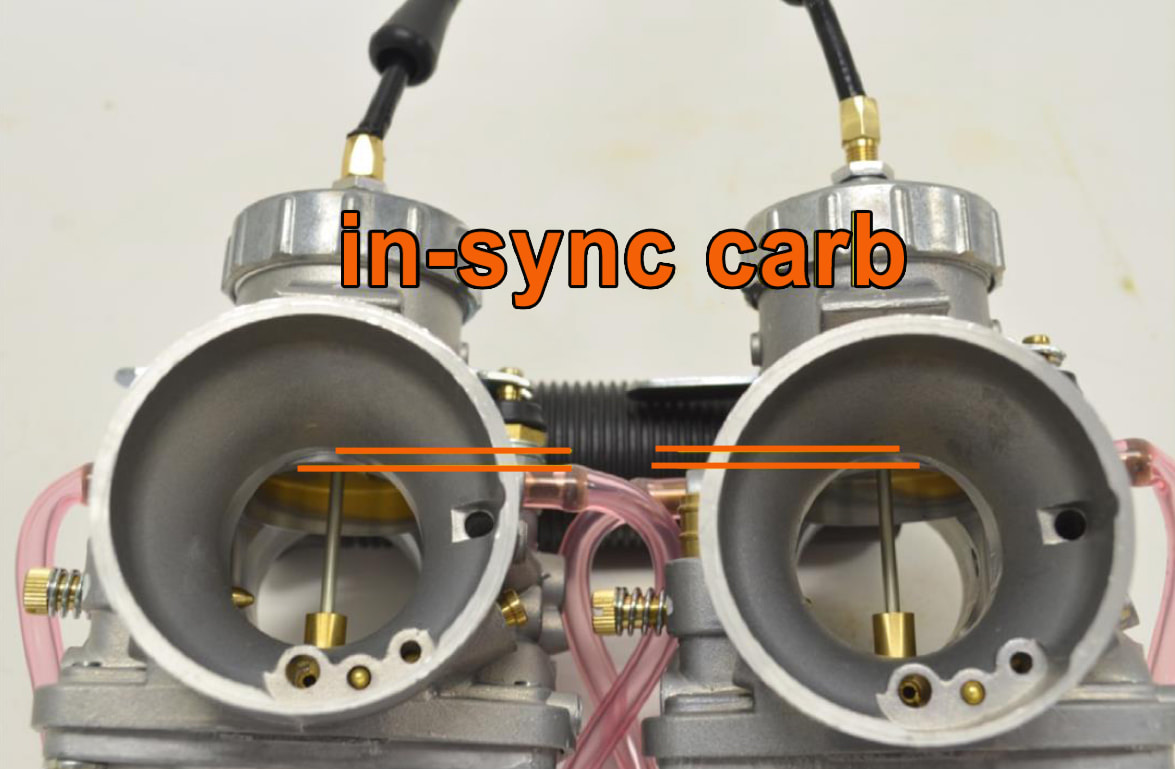
Static Syncing Procedure If you can get yourself into position to do so, take a look down the intake bells of the carbs. If you can't get into a position to do that, you can use a mirror or, you can use your finger to feel the edge of the throttle slides (although this takes more experience). Rotate the twist throttle until the top edge of one of the slide cutouts is flush with the top edge of the intake bell.
If you take a moment to look at photo on the above left, you'll notice the throttle slide on the right carburetor is about ¼” lower than the slide on the left carburetor. The throttle slide on the left carburetor is even with the edge of the intake bell. When installing new carbs, you'll find in almost every case, the throttle slide on one carb will be lower than the other carb. It's usually easiest to adjust the carb with the lowest slide.
|
Syncing carbs off the bike Here’s a hint that might prove to be really helpful for someone syncing carbs for the first time. Depending how long and accessible your throttle cable is, you may be able to sync the carbs off the bike. If you can easily remove the carbs and the throttle, you may be able to sync the carbs remotely, off the bike. This is known as "bench syncing." Either of these methods are preferable to syncing on the bike because you can look directly down the bell of the carburetor to see what you are doing, unimpaired by frame tubes, battery boxes or air cleaners. If your throttle assembly has electrical switches incorporated into it, it may be too much trouble to disconnect the electrical to remove the throttle assembly for bench syncing, but you may still be able to sync off the bike as in the photo above. |
In the situation shown in the above left photo, the twist throttle was released the throttle slides were checked for slack. It was found the right carb had about 3-4mm of play in the cable. The adjuster on the top of the carb was backed out (turned counterclockwise) until the adjuster was snug against cable. The test was run again, slowly twisting the throttle until the base of the left slide touched the top of the intake bell. It was again compared to the slide on the right and they were closer, but not perfect. It took one more adjustment of a turn or two on the cable adjuster to bring the right carb perfectly to the edge of the intake bell. The right side was now identical to the left (see the picture on the right). The carbs were synced!
- Note: Don't jump around, adjusting one side and then the next. Use whichever carb has the higher throttle slide as a baseline and do all your adjustments on the other.
A note on smooth bore carbs
With some of the banked, smooth-bore carburetor sets you see installed on inline 4-cylinder bikes (like the CB550), they can only be bench synced off the bike. They cannot be vacuum synced on the bike. That is because the sync adjustments are under the top covers of the carb and the bike can't be run without the carb tops on. What were these engineers thinking?
With some of the banked, smooth-bore carburetor sets you see installed on inline 4-cylinder bikes (like the CB550), they can only be bench synced off the bike. They cannot be vacuum synced on the bike. That is because the sync adjustments are under the top covers of the carb and the bike can't be run without the carb tops on. What were these engineers thinking?
Tuning and jetting the bike
With the installation complete, you're ready to move onto jetting the bike. This process is overlooked by many, but it is the only way you'll ever get optimal performance out of your motorcycle. The procedures outlined here can be applied to both single and multiple carb applications.
Initial start up sequence
It's important to follow these simple steps (in sequence) as your perform your initial start up.
- Pull the spark plugs out of the bike. If the plug insulators (the bottom, ceramic part of the plug) are dark, sooty or fouled, install new spark plugs.
- Check the high tension leads (plug wires). Make sure none of the leads are broken or lose. Also, be sure the plug caps are firmly seated on the plugs.
- Check your engine oil (always a good idea when a bike has had maintenance).
- Turn on the fuel at the petcock and check for leaks. DO NOT ATTEMPT TO START THE BIKE IF THE CARBS ARE LEAKING FUEL. THIS IS A SERIOUS FIRE HAZARD. If there are leaks, resolve them and clean up any fuel that has spilled onto the bike or floor before proceeding.
- Push down the choke lever to engage the Mikuni starter circuit. On bikes with two-cylinders, you can usually start the bike successfully with just one choke unless it’s really cold.
- Make sure the bike is in neutral before cranking. Confirm by rolling the bike back and forth.
- Keep the throttle closed and do not open it while starting. If you twist the throttle with the choke lever down, you will defeat the choke circuit on the Mikuni carb.
- Pull in the clutch and press the starter button. If the bike does not have electric start, the clutch may have to be released prior to kickstart depending on the type of clutch.
- If the timing is set and valves are adjusted properly, the bike should fire right up. Once the engine is warm, you will need to adjust the idle on the bike. If you are working with multiple carbs, adjust each carb in matching increments.
- After the engine is warm and the idle has been set, adjust the fuel mixture screw (see instructions below).
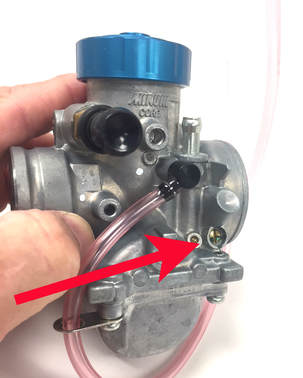 This is an air-mixture screw because it's on the air intake side of the carb
Adjusting the mixture screw
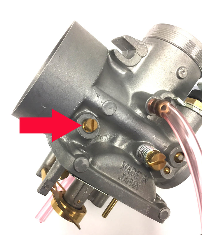
The mixture screw (also referred to as the air-mixture screw, fuel-mixture screw, idle-mixture screw or pilot screw) works in concert with the pilot jet. The mixture screw is used to adjust the fuel mixture at idle. This screw has no effect on the mid-range or top-end mixture settings. It is important to have this screw adjusted properly or the bike may run rich or lean at idle.
If a carburetor has this mixture adjustment screw located closer to the air intake side of the carb (air cleaner side), this will normally be referred to as the air-mixture screw. If the screw is located nearer to the spigot or flange mount side of the carb (nearest to the engine), then it is called a fuel-mixture screw.
During the initial start up, if you find the bike is able to idle, then you're pretty close on your pilot jet setting. You should at this time go ahead and adjust the mixture screw. The procedure will be explained below, first with a single-cylinder engine, and then with a twin-cylinder engine.
Single Cylinder Engine:
- Screw in the mixture screw all the way. Do not tighten the screw as the seat for the screw can be easily damaged. Now open the screw 1-1/4 turns. This approximates where the screws are placed when delivered from the factory.
- Warm the engine to a normal operating temperature.
- Open the air adjustment screw slowly, turning it counterclockwise, until there is a rise in RPMs
- Continue opening the screw slowly until the RPMs peak, level off and then start to drop.
- Once the RPMs begin to drop, turn the screw the opposite way until you again hit peak RPMs.
- With the RPMs at peak, enrichen the mixture by turning the screw approximately 1/4 turn. The direction depends on type of mixture screw you have. If your carb has an air-mixture screw, turn the screw clockwise to enrichen. If you have a fuel-fuel mixture screw, turn the screw counterclockwise to enrichen (see paragraph above describing the mixture screws).
- Screw in the mixture screw all the way on both carburetors. Do not tighten the screw as the seat for the screw can be easily damaged. Now open the screws on both carburetors 1-1/4 turns.
- Warm up the engine to normal operating temperature and shut the engine down.
- Remove the spark plug cap off one cylinder. NOTE: If you have an electronic ignition, place a spare spark plug into the cap and ground it against the cylinder head. An electronic ignition can be ruined by running the motorcycle with the spark plug cap off if the cap is not grounded. If you have a points ignition, you don’t have to worry about grounding the spark plug. CAUTION: DO NOT TOUCH THE EXPOSED SPARK PLUG WITH THE BIKE RUNNING; THIS COULD RESULT IN SEVERE ELECTRICAL SHOCK.
- On the side with the spark plug cap still attached (the running side), adjust the idle up with about a half-turn of the idle screw. Take note of the amount the idle screw is turned so it can be returned to where it was before starting. Adjust the idle up the same amount on the other carb as well
- Start the bike. If the idle is too low, adjust the idle up until the bike is idling on one cylinder. Adjust the carburetor on the non-running side by the same amount
- Open the air adjustment screw slowly, turning it counterclockwise, until there is a rise in RPMs
- Continue opening the screw slowly until the RPMs peak, level off and then start to drop
- Once the RPMs begin to drop, turn the screw the opposite way until you again hit peak RPMs
- With the RPMs at peak, enrichen the mixture the screw approximately 1/4 turn. If your carb has an air-mixture screw, turn the screw clockwise to enrichen. If you have a fuel-fuel mixture screw, turn the screw counterclockwise to enrichen (see paragraph above describing the mixture screws)
- Repeat procedure on the other cylinder.
- With the mixture screws set, adjust the idle as necessary with equal turns on both carbs.
- If you are unsure about whether or not the idle is adjusted properly, repeat the procedure in the above paragraph: Setting the idle position.
Carburetor Jetting
Unless you’re really, really lucky, the chances of you installing a new carburetor and having it work perfectly without any adjustments are slim – extremely slim. Of course, if you’re buying a set of carburetors that have been pre-jetted for your specific make and model, then the chances are pretty good that the jetting is close or even spot on, but the possibility still exists that some minor adjustments might have to be made to make the bike run right.
We stated back at the beginning of this tutorial that you don’t want to get carbs that are too big or too small for your bike. If you’re the first guy to put Mikuni pumper carbs on a 1958 Ariel Square Four, you’re going to have to do some experimenting to get the jetting right. But the internet is a wonderful thing. Information is available at our fingertips that years ago may have taken years to uncover. For example, if you decide you want your old Husky CR400 to start quicker by installing a Mikuni aftermarket carb, you might very well be able to find someone in a Husqvarna or vintage motocross user group who has made that swap before and figured out the necessary jetting. More than likely, they’ll be happy to share what they’ve learned. The information you may be able to get from a user group could prove invaluable. Why reinvent the wheel if you don’t have too? Of course, you shouldn't take information gleaned from a user's group as gospel. Even if your bike seems like it's running good on somebody's jetting recommendation, it is always a good idea to perform tests (as described below) to make sure you are not running lean or rich.
Pre-Tuning Priority
This has been mentioned before, but it's worth mentioning again. Before you begin adjusting or re-jetting a carburetor, you have to be sure the engine is mechanically sound. Otherwise, your attempt to adjust the carbs could prove unsuccessful and aggravating.
This has been mentioned before, but it's worth mentioning again. Before you begin adjusting or re-jetting a carburetor, you have to be sure the engine is mechanically sound. Otherwise, your attempt to adjust the carbs could prove unsuccessful and aggravating.
- Using a compression gauge, check the cylinder compression of the engine to be sure it is meeting factory specs (or pretty darned close). If you're dropping under a 90 pounds, you've probably are experiencing an issue. You also might have a problem if your bike is belching blue smoke or and your spark plug is oily. On a multi-cylinder engine, check all cylinders and confirm that each cylinder is within 10 pounds of the others.
- Check the clearance in the valves and if they are off, adjust to factory tolerances.
- Ignition timing - If you're using a system with points, make sure the points are in good shape and set to factory specs. Your spark advance has to be working correctly as well. If the springs are hanging on by a thread, you'll need to address that as well.
- Make sure ignition system is in good shape - that means a fresh spark plug(s) that is gapped correctly. You'll also need to make sure the high tension lead (spark plug wire) is in good shape. If it's cracked or if the spark plug cap is in poor shape, you should replace it.
- Install a clean air filter and make sure air-box boots and other connections are secure. A dirty air filter can seriously restrict air flow. If your air box boots are cracked or loose, you might be increasing air flow that isn't compensated for by the carb and that air also will not be filtered in any case.
- Fuel System - make sure you are running clean and filtered fuel - see inset above "Notes on fuel."
- Exhaust - Be sure to check for leaks around the exhaust manifold where it connects to the header. Also check for leaks between the header and muffler. If you have exhaust leaks, you'll no doubt hear popping on deceleration. If you can hear your baffle rattling around in your muffler or if your bike's been getting louder lately, you might need to check the packing around the baffle.
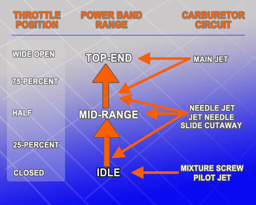
The stages of adjustment
When dialing in your jetting you need to start with the idle circuit and build upon that. Once you finish the idle circuit, you can move on to jetting the mid-range, and then the top end settings. You have to work in this progressive, bottom-up sequence because each circuit is additive. That means each component works in concert with the component that precedes it. If the preceding circuit isn't correct, the one that follows likely won't be either.
Take a look at the diagram on the right. At the bottom of the diagram, you'll see the throttle is closed, and the idle range is being controlled by the pilot jet and mixture screw. As soon as you begin lifting the throttle, the cutaway in the throttle slide begins taking over as the engine revs into the mid-range. The idle circuit doesn't stop working. But, its affect is minimized because the cutout on the throttle slide is drawing in a much greater fuel/air mixture. Even though the pilot jet is still providing fuel, the amount is so minimal, it has no real effect on on this end of the performance range.
|
Adjusting and testing the pilot circuit As mentioned earlier, the pilot jet (idle or slow speed circuit) and the air screw work together to supply fuel to the engine at idle and the lowest power 83-=88settings. If your bike is idling, then you are probably pretty close to the correct pilot jet size. Well get to what to do if the bike is not idling a little later, but let's start with the presumption that the bike is idling. Follow the procedure outlined below to check your pilot jet:
|
Indexing your throttle settings
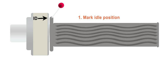
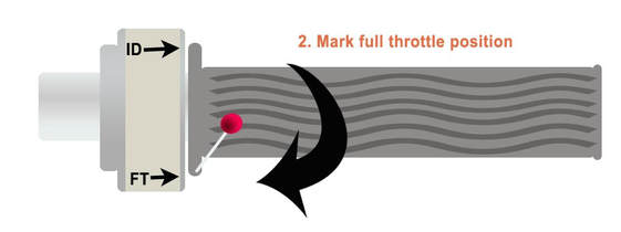
This simple procedure will take just a couple of minutes and it will go a long way toward helping you identifying issues as you tune your bike. Early on, we talked about how Mikuni’s different fuel metering systems worked in relation to various throttle positions. One easy way to visualize theses stages of fuel flow is to identify the throttle settings and how they correspond with the controlling elements of the carburetor. What you are doing in this exercise is providing yourself with a visual reference as to what part of the power band is controlled by what parts of the carburetor. This makes it much easier to isolate and identify issues while tuning. To do this, you'll need a stick pin, some masking tape, a marker and a tape measure. Referring to the illustrations below, start by placing a piece of masking or duct tape onto the top side of the throttle assembly. At the top of the tape, mark a point indicated a closed throttle or idle. In this illustration, the lettering "ID" indicates idle position. A mark or arrow is dawn and a stick pin is placed in the rubber edge of the hand grip aligning with the idle mark. Next. Open the throttle fully. Where the pin stops, place another mark or arrow and label it FT for full throttle (see illustration below).
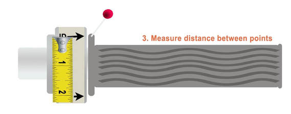
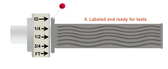
With the full rotation of the throttle marked as ID and FT, measure the distance between ID and FT points and place a mark for the center point and equal distances between the two end marks. Note the the tape measure is just for illustration purposes, and more than likely will not be the same as your measurement.
When everything is marked you have a perfect gauge for determining what part of the power band is in play and where you might be having issues (see illustration below):
|
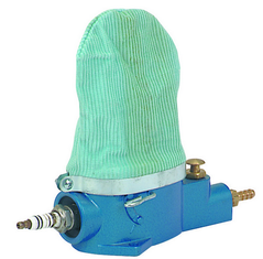 The Harbor Freight plug cleaner costs about $15 and does a great job
Keep in mind, your plugs are not always going to fall into the range of either black and white. Often, you'll find the color of the insulators are somewhere in between black and white. For example, let's say your plug isn't a nice caramel, but it's a darker white maybe even a light tan. Close but not exactly where you want to be. That color would indicate you're not far off from having the mixture dialed in, but you're still a bit lean. So rather than put in a larger pilot jet, you might just try enrichening the mixture a bit with the mixture screw. Just make sure you turn the mixture screw in the right direction (see Adjusting the Mixture Screw). The opposite would be true if you found an insulator that was a bit gray rather than black or sooty. In that case you would be slightly rich and you'd want to try to lean the mixture out a bit with the mixture screw before re-jetting.
If you find you need to re-jet, you are going to have to run through the jetting test described above. And, that will require installing new spark plugs. This can get expensive if you end up installing a half-a-dozen or more plugs (which you will). If you have a compressor, you can spend about $15 and get get an inexpensive plug cleaner. Unfortunately, the insulators on spark plugs can't be properly cleaned by just dipping them in gas, spraying them off with carb clean or running them under a wire wheel. The only way to make the insulator resemble a new plug is by bead-blasting the plug. Harbor Freight makes an inexpensive, plug blaster you can buy on-line, or in one of their many stores across the country.
Please be aware that media used in a bead-blaster (even the little spark plug blaster) can seriously damage an engine. If you get this material in the cylinder it can wear out the rings, piston and cylinder very quickly. That is why I recommend after blasting the spark plug, you spray if off with an alcohol cleaner (like brake clean) and then blow it off with compressed air.
Even with a plug cleaner, you'll still want to have several new spark plugs standing by for the test.
If you find re-jetting is necessary, you'll need to follow these procedures:
- Install the new pilot jet
- Start the engine (with the dirty plug from the previous test) and let it warm to operating temperature. If the plug is deeply fouled (very black) put in a clean plug
- Set the idle speed and adjust the air mixture screw (see directions above)
- Shut down the engine and remove the spark plug (careful, the plug will be hot - you might want to have a leather glove handy to grab the plug once it is ready to come out
- Install a new or freshly cleaned plug (do not use a dirty plug - this defeats the purpose of the test)
- Start the engine and let it run at idle for approximately 5 minutes
- Do not accelerate the engine above idle during this time
- Stop the engine with the key switch or kill button. Do not stop the engine by choking.
- Let the engine cool
- Remove the spark plug(s) and check the color
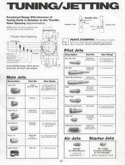
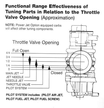 This cart from Mikuni shows in detail the relationship between components and throttle range
Adjusting and testing the mid-range fuel mixture
As mentioned before, if you divided the throttle into four equal segments, the first 25 percent would be controlled by both the pilot circuit (at idle only) and the cutaway in the throttle slide (valve). At the moment the throttle is lifted, the little crescent cutaway in the throttle slide begins to allow more air into the fuel air mixture. This is indicated by the chart on the right that can be found in the Mikuni products catalog. Simultaneously, the needle jet is picking up fuel from the float bowl and matching it to the increased air volume provided by the opening of the throttle slide cutaway.
As the RPMs climb, and engine moves from the first 25 percent to 50 percent power, the jet needle moves up through the needle jet exposing opening in the jet and allowing more fuel to mix with increased air now flowing from a large opening in the throttle slide. If you were to look down the venturi of your carburetor, you would see that it is about half blocked by the throttle slide.
As the throttle slide is lifted, the bike advances into the upper end of the mid-range. This is typically know as the "cruise" settings. When you're riding on the highway (unless you're on a really small bike), the engine isn't normally being run at full throttle, it's usually in the 3/4 throttle range. During this time, the jet needle has the largest effect on the fuel mixture. On most Mikuni carbs, the jet needle is adjustable.There are usually four or five positions where the needle can either be raised or lowered using by moving the E-clip (more on that a little later). When the needle is lower in the jet, it allows less fuel and a leaner mixture. When the needle is raised, more fuel flows through the needle jet and creates a richer condition.
It is important to note these components work together seamlessly so it can sometimes be difficult to pinpoint exactly what component is causing an issue. That is why, when working within the mid-range, you often start with the easiest and cheapest method of adjustment - and that is moving the clip on the jet needle. Let's talk a little more about this important component. To eliminate confusion, we'll refer to the jet needle as the needle, and we'll call the needle jet, the jet. At idle, the needle sits inside the jet blocking fuel intake. The needle is attached to the throttle slide (throttle valve) and protrudes out the bottom. As the slide is pulled up by the throttle cable, the needle follows. With the needle higher in the jet, the amount of fuel entering the mixing chamber is increased until reaching 3/4 throttle. From 3/4 throttle to full throttle, the needle raised out of the jet, eliminating any obstruction and allowing the maximum amount of fuel to flow through the main jet into the mixing chamber. On many Mikuni carbs, the main jet is either attached to or sharing the same chamber as the needle jet. One more thing about the needle. These jet needles are available in many sizes to fine tune fuel flow. The are available in both single taper and double taper with a wide variety of sizes available for most carbs (see the chart below).
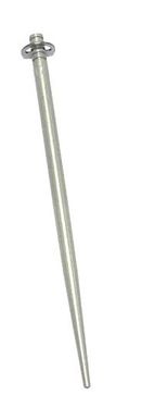
Getting back to the jet, it's really easy to adjust how high or how low the needle sits in the jet. This is done by moving the e-ring or jet needle positioning clip. This little clip fits inside the grooves on the top of the needle. There are usually 5 grooves in most Mikuni needles. The clips come installed in the center groove from the factory.
As discussed before, to make the mid-range leaner, you would raise the clip to a higher notch, which would drop the needle deeper into the jet. This restricts fuel flow. Conversely, to make the mixture richer in the mid-range, you would place the clip in a lower notch, which would raise the needle. This would allow more fuel to pass through the jet.
Should you find that raising or lowering the needle does not have enough effect in the lower part of the mid-range (25-50 percent), you can often compensate by installing a different throttle slide with either a larger or smaller cutaway. The larger cutaway will allow in more air, making the mixture leaner. A smaller slide cutaway would enrich the mixture. Mikuni offer slides for their round slide carbs in 4 to 5 different sizes. Flat slide carbs generally do not offer as many sizes.
If you find the mid-range is good between 25-50 percent throttle but is problematic between 50-75 percent throttle, a new jet or needle may be required. Mikuni offers several needle jet sizes and as mentioned before, a wide variety of needles as well.
If at anytime during testing you change the position of the needle, the needle itself, the jet or the throttle slide, you will need to perform a plug check relative and specific to that range of performance (i.e, low mid-range, cruise, etc). It is also highly recommended that you don't make more than one change at a time, for instance lowering the needle clip and, at the same time, installing a smaller jet. Doing this can skew your test results. If you noticed a significant change in the mixture, you wouldn't know if it was due to the needle position or the jet.
Lower mid-range plug check:
Note: this procedure should only be performed once you have achieved the correct setting for the pilot or idle circuit and verified with a plug check.
If you find the spark plug insulator is a nice caramel color (see plug color chart above), your jetting is right where it needs to be. If you are leaning towards the lean (white) side, you might try dropping the clip (and raising the needle) on your jet needle one notch and performing the test again with a fresh plug. This will allow intake of more fuel in the mid-range. If you find you are on the rich side, you might try raising the clip (and dropping the needle) to limit the intake of fuel in the mid-range. Remember, there are other components that alter the fuel/air mix of the mid-range including the slide cutout, jet needle size as well as the needle jet size.
Once you have achieved that nice caramel color with the spark plug insulators, you can move onto adjusting the top-end rpm mixture.
Note: this procedure should only be performed once you have achieved the correct setting for the pilot or idle circuit and verified with a plug check.
- You will need a spark plug wrench and a fresh set of spark plugs. Since you be on the road for this test, don't forget to take them with you. Find an area where you can safely work on the bike (away from traffic) and then ride the bike at mid-rpm levels (50-percent throttle) for 3-5 minutes. If there are stop signs or traffic lights, this won't do. If your RPMs are limited by speed limits, you can use a lower gear (2nd, 3rd, 4th) to keep the speed down. It is imperative with this test, that once the test has begun, you do not vary the mid-range RPMs for 3-5 minutes.
- Start the engine (with the dirty plug from the previous test) and let it warm to operating temperature. If the plug is deeply fouled (very black) put in a clean plug.
- Once the bike is warm, install a new plug.
- Take the bike out on the road, keeping the RPMs steady at about 50% throttle for approximately 3-5 minutes.
- One you have a safe place to pull off, shut down the bike without backing off the throttle. This can be done using the using the kill switch or kill button. Do not let the bike return to idle with the engine running. Coast to a safe stopping point where you can work on the bike (preferably a parking lot or turn-out safely away from traffic).
- Either let the bike cool for about 10 minutes or, if the bike is still hot, use a pair of leather gloves to remove the spark plug (careful, the plug, engine and exhaust will be extremely hot and you can get burnt even with gloves on).
- With the spark plug(s) out, and check the color. If you are on a multi-cylinder motorcycle, you will need to check all plugs.
If you find the spark plug insulator is a nice caramel color (see plug color chart above), your jetting is right where it needs to be. If you are leaning towards the lean (white) side, you might try dropping the clip (and raising the needle) on your jet needle one notch and performing the test again with a fresh plug. This will allow intake of more fuel in the mid-range. If you find you are on the rich side, you might try raising the clip (and dropping the needle) to limit the intake of fuel in the mid-range. Remember, there are other components that alter the fuel/air mix of the mid-range including the slide cutout, jet needle size as well as the needle jet size.
Once you have achieved that nice caramel color with the spark plug insulators, you can move onto adjusting the top-end rpm mixture.
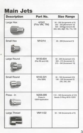 Mikuni's main jet styles
Adjusting and testing the top-end fuel mixture
The top end fuel mixture is controlled by the main jet. The main jet begins to kick in at about 75-percent throttle. By this time, the needle is almost completely out of the needle jet and there is noting blocking the path of the fuel from the main jet. But remember, each component is additive. So while the main jet is at the top of the food chain, the pilot jet, slide cutaway, jet needle and needle jet all all working together for add to the fuel/air mixture. That is why it is so important that the idle and mid-range components are properly adjusted before moving onto the main jets.
Mikuni has several different styles of main jets. The most typical are the large hex style and the large round style. You can use the Mikuni chart on the right to determine what type of jet you have. This chart also provide the various size ranges available for each style jet.
If you're working on a vintage motorcycle with a Mikuni OEM carb, you might be surprised to find your main jet is still available.
Top-end plug check:
Note: this procedure should only be performed once you have achieved the correct settings for the pilot and mid-range components and have verified them with a plug check.
Once again, if you find the spark plug insulator is a nice caramel color (see plug color chart above), your jetting is right where it needs to be. If you are leaning towards the lean (white) side, you will want to step up to a larger main jet. You should do this in relatively small increments. If you have a 150 main jet, you might want to try a 155 or 160 main. Do not make big jumps in jetting. For instance, don't jump from a 150 to a 175. Remember, you are trying to narrow the scope of your search. Making big jumps doesn't help.
Once you have achieved that nice caramel color with the spark plug insulators, you can move onto adjusting the top-end rpm mixture.
Once you have have the fuel mixture dialed in, you'll notice your bike will perform significantly better. Please keep in mind, this is a generalized guide to tuning and jetting a Mikuni round-slide carburetor. This does not provide all the answers to all carburetor issues. But, this is really valuable information for anybody who works on motorcycles - from weekend warriors to pros. It's also good to note, that while the design of the carbs may differ, most of these principals in apply to Kehin, Delorto, Bing, Hatachi, Weber or almost any other carburetor.
Carburetor tuning is a science - one that takes years to master. There are ways to fine tune a particular section of the power-band as well as some less-critical components, like the air jet (a part of the high speed circuit which enriches the mixture as the RPMs increase), that aren't covered here. This is not a course on mastering the carburetor, rather a straight forward guideline to help mechanics with the basics of tuning and jetting. There's enough information here to satisfy most tuning needs. Not enough for those in racing circles or perfectionists, but enough for the average mechanic and layman.
You'll find there also isn't much information on diagnosing carburetor problems. This tutorial will note some of the easily identifiable carburetor symptoms, but issues related to a poorly running motorcycle may be inaccurately linked to the carb when it is really rooted with ignition, valve timing, valve adjustment or compression issues. Of course, a competent mechanic, through a series of tests, will eventually find the root case of these issues, but it's not always straight forward or obvious. And, these types of issues are not covered in this tutorial.
Note: this procedure should only be performed once you have achieved the correct settings for the pilot and mid-range components and have verified them with a plug check.
- As you did with the mid-range check, you will need a spark plug wrench and several fresh spark plugs. Since you be on the road for this test, don't forget to take them with you. Find an area where you can safely work on the bike (away from traffic) and then ride the bike at high-rpm levels (75-percent throttle) for 3-5 minutes. If there are stop signs or traffic lights, this won't do. If your RPMs are limited by speed limits, you can use a lower gear (3rd or 4th) to keep the speed down. It is imperative with this test, that once the test has begun, you do not vary the mid-range RPMs for 3-5 minutes.
- Start the engine (with the dirty plug from the previous test) and let it warm to operating temperature. If the plug is deeply fouled (very black) put in a clean plug.
- Once the bike is warm, install a new plug.
- Take the bike out on the road, keeping the RPMs steady at about 75-100% throttle for approximately 3-5 minutes. Be careful to obey all speed laws and do not go faster than your ability to ride the bike safely.
- One you have a safe place to pull off, shut down the bike without backing off the throttle. This can be done using the using the kill switch or kill button. Do not let the bike return to idle with the engine running. Coast to a safe stopping point where you can work on the bike (preferably a parking lot or turn-out safely away from traffic).
- Either let the bike cool for about 10 minutes or, if the bike is still hot, use a pair of leather gloves to remove the spark plug (careful, the plug, engine and exhaust will be extremely hot and you can get burnt even with gloves on).
- With the spark plug(s) out, and check the color. If you are on a multi-cylinder motorcycle, you will need to check all plugs.
Once again, if you find the spark plug insulator is a nice caramel color (see plug color chart above), your jetting is right where it needs to be. If you are leaning towards the lean (white) side, you will want to step up to a larger main jet. You should do this in relatively small increments. If you have a 150 main jet, you might want to try a 155 or 160 main. Do not make big jumps in jetting. For instance, don't jump from a 150 to a 175. Remember, you are trying to narrow the scope of your search. Making big jumps doesn't help.
Once you have achieved that nice caramel color with the spark plug insulators, you can move onto adjusting the top-end rpm mixture.
Once you have have the fuel mixture dialed in, you'll notice your bike will perform significantly better. Please keep in mind, this is a generalized guide to tuning and jetting a Mikuni round-slide carburetor. This does not provide all the answers to all carburetor issues. But, this is really valuable information for anybody who works on motorcycles - from weekend warriors to pros. It's also good to note, that while the design of the carbs may differ, most of these principals in apply to Kehin, Delorto, Bing, Hatachi, Weber or almost any other carburetor.
Carburetor tuning is a science - one that takes years to master. There are ways to fine tune a particular section of the power-band as well as some less-critical components, like the air jet (a part of the high speed circuit which enriches the mixture as the RPMs increase), that aren't covered here. This is not a course on mastering the carburetor, rather a straight forward guideline to help mechanics with the basics of tuning and jetting. There's enough information here to satisfy most tuning needs. Not enough for those in racing circles or perfectionists, but enough for the average mechanic and layman.
You'll find there also isn't much information on diagnosing carburetor problems. This tutorial will note some of the easily identifiable carburetor symptoms, but issues related to a poorly running motorcycle may be inaccurately linked to the carb when it is really rooted with ignition, valve timing, valve adjustment or compression issues. Of course, a competent mechanic, through a series of tests, will eventually find the root case of these issues, but it's not always straight forward or obvious. And, these types of issues are not covered in this tutorial.
Diagnosing Carburation Issues
Poor Idling:
Poor idling can be caused by too much or too little fuel or air in fuel/mixture. Perform a idle circuit spark plug test as described
in the “Adjusting and Testing the Idle Circuit” section above. That way you can determine if the symptom(s) you are experiencing are related to a rich or lean condition
Symptom
After testing the pilot circuit (described above), if the color of the spark plug insulator is a dark-colored to black, you have a rich condition and may experience one or more of the following symptoms:
After testing the pilot circuit (described above), if the color of the spark plug insulator is dull to bright white, you have a lean condition and may experience one or more of the following symptoms:
|
Solution
Note: It is important to only try a single solution and retest. Do not attempt mulitiple solutions at one time! |
Poor Initial Acceleration and Mid-range acceleration :
Using the instructions in the “Adjusting and testing the mid-range fuel mixture” section above, run a mid-range spark plug test. That way you can determine if the symptoms below are related to a rich or lean condition.
Symptom
After mid-range testing (described above), if your spark plug insulator is dark-colored to black, you have a rich condition and may experience one or more of the following symptoms:
After mid-range testing (described above), if your spark plug insulator is dull to bright white, you have a lean condition and may experience one or more of the following symptoms:
|
Solution
Note: It is important to only try a single solution and re-test. Do not attempt multiple solutions at one time! |
Poor Cruise Performance :
Review the instructions above for a top-end spark plug test. Proceed as you would for a top-end test except to reduce the RPM about 25 percent from wide open setting. This will provide a good setting for a cruising-range spark plug test. That way you can determine if the symptoms below are related to a rich or lean condition.
Symptom
After cruise testing, if your spark plug insulator is dark-colored to black, you have a rich condition and may experience one or more of the following
symptoms:
After cruise testing, if your spark plug insulator is dull to bright white, you have a lean condition and may experience one or more of the following symptoms:
|
Solution
Note: It is important you only try a single solution and re-test. Do not attempt multiple solutions at one time!
|
Poor Top-End Performance :
Review the instructions in the “Testing and adjusting the top-end fuel mixture section” and run a top-end spark plug test. That way you can determine if the symptoms below are related to a rich or lean condition
Review the instructions in the “Testing and adjusting the top-end fuel mixture section” and run a top-end spark plug test. That way you can determine if the symptoms below are related to a rich or lean condition
Symptom
After top-end testing (described above), if your spark plug insulator is dark-colored to black, you have a rich condition and may experience one or more of the following symptoms:
After top-end testing (described above), if your spark plug insulator is dull to bright white, you have a lean condition and may experience one or more of the following symptoms:
|
Solution
|
