Suzuki DR350 Pre-Jetted Carburetor Conversion
Installation Instructions
NOTE: This manual is provided as technical reference tool to assist experienced mechanics in the installation of the Niche Cycle, DR350 Mikuni carb kit. This manual in no way replaces the experience and skill necessary to safely and property install a motorcycle carburetor. It is assumed these kits will only be installed by professionally trained motorcycle mechanics. Niche Cycle, The Vintage Bike Builder and all associated parties accept no liability for any damage, or injury resulting from the incorrect installation or maintenance of any carburetor. Please use this guideline at your own risk.
The DR350 - Mikuni TM33 Conversion Kit is a very straight forward carburetor upgrade for the DR350. With these instructions, anyone with basic mechanical skills and a few tools can tackle the job. The TM33 has a built in fuel pump which provides unparalleled throttle response. And being a Mikuni, quick starting and easy maintenance are always present. Unlike the OEM Mikuni carburetor, replacement parts for this carb are readily available.
 1999 DR350 with electric start
Fitment
This kit will fit all models of the 1990-2001 Suzuki DR350. This kit was designed to replace the stock Mikuni CV carb that came with DR350SE (electric start models) beginning in 1994. However, all DR350s can benefit with the use of the TM33.
NOTE: While other models are very similar; these instructions apply specifically to the DR350 electric start models. The test bike used for these instructions was a 1999 DR350SE. If your bike is not the same year or model, you might find slight differences, but the installation is basically the same.
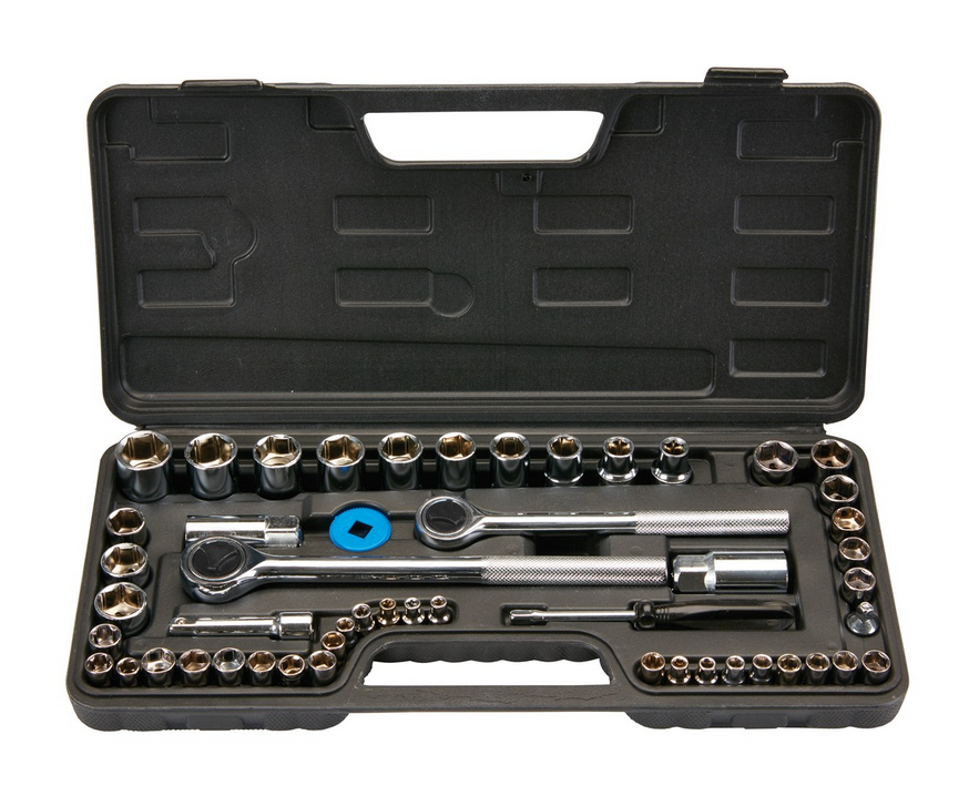 A socket set like this will set you back less than $15 at Harbor Freight and can be ordered online if there isn't a store near you
The Tools you’ll need
Make it easy on yourself and use the right tool for the job. If we’re very specific about a tool, it’s because using anything else will eventually cost you time and money. If you don’t have the right too, get it and save yourself a lot of aggravation. If you try to use tools like an adjustable wrench or a vice grip, you’ll round-off the nut or bolt and have to replace it. With metric tools so cheap and available on Amazon, eBay or Harbor Freight, it’s just penny wise and pound foolish not to get the right tool.
One of the best tools you can use is a cell phone or digital tablet. Professional mechanics used to draw a lot of diagrams, but these days, they take lots of pictures. Some keep a spiral bound notebook handy for taking notes. These notes and pictures save a lot time and frustration on projects – especially when you are disassembling something you are unfamiliar with.
If you own a motorcycle, you should have all of the tools listed below and more to maintain your bike. Rather than list the individual sockets or wrenches, I have put them down as kits, because that’s how they are normally sold. You won’t need all the wrenches or sockets for this just, but it makes more sense to buy the kit than buying these tools individually.
Here is a list of tools and items you will need:
Primary disassembly
Make it easy on yourself and use the right tool for the job. If we’re very specific about a tool, it’s because using anything else will eventually cost you time and money. If you don’t have the right too, get it and save yourself a lot of aggravation. If you try to use tools like an adjustable wrench or a vice grip, you’ll round-off the nut or bolt and have to replace it. With metric tools so cheap and available on Amazon, eBay or Harbor Freight, it’s just penny wise and pound foolish not to get the right tool.
One of the best tools you can use is a cell phone or digital tablet. Professional mechanics used to draw a lot of diagrams, but these days, they take lots of pictures. Some keep a spiral bound notebook handy for taking notes. These notes and pictures save a lot time and frustration on projects – especially when you are disassembling something you are unfamiliar with.
If you own a motorcycle, you should have all of the tools listed below and more to maintain your bike. Rather than list the individual sockets or wrenches, I have put them down as kits, because that’s how they are normally sold. You won’t need all the wrenches or sockets for this just, but it makes more sense to buy the kit than buying these tools individually.
Here is a list of tools and items you will need:
- A flat blade screwdriver set
- A Phillips-head screwdriver set
- Metric Hex Key (Allen wrench) set
- Metric combination wrench set (6mm-19mm)
- Metric socket set (6mm-19mm)
- Razor knife (for cutting hose)
- Plastic prying tool (see note below)
- Needle nose pliers
Primary disassembly
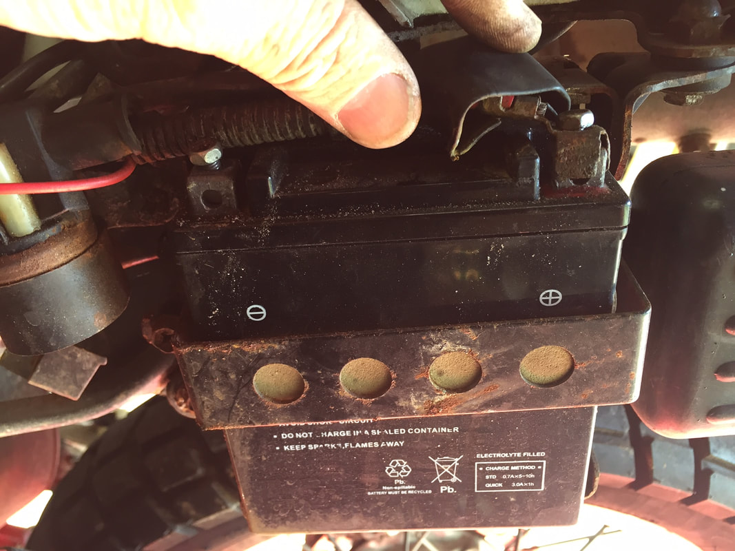 To avoid creating sparks around fuel, be sure to disconnect the battery
- Remove side panels using a #3 Phillips screwdriver.
- Disconnect the negative terminal for the battery using a screwdriver, 8mm or 10mm wrench (depending on battery bolts).
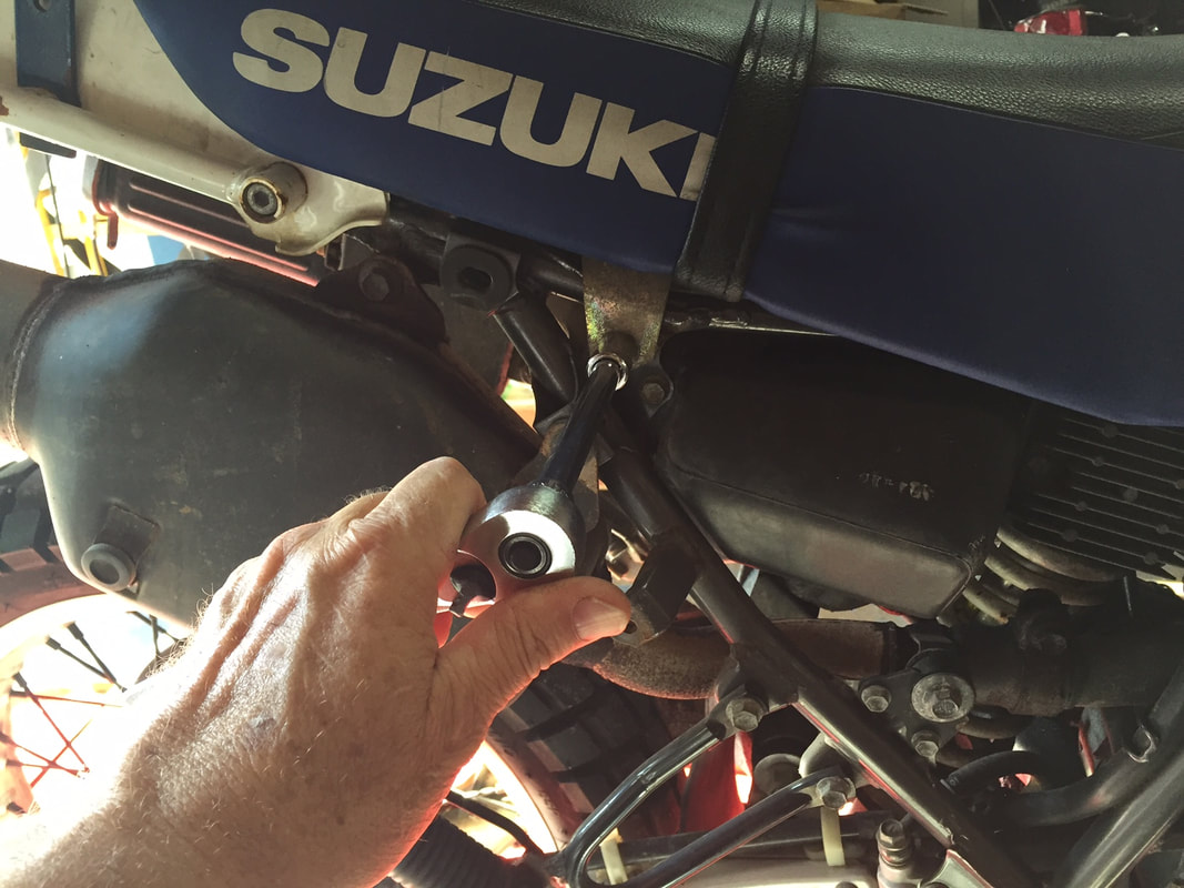
- Remove the two bolts securing the rear of the seat with a 12mm wrench. Lift the seat from the rear, and pull back to remove it. These bolts can be found just above and behind the air box.
- Turn off the fuel at the petcock. If the fuel line still has the factory clamp, use a pair of pliers to squeeze the clamp and move it down the fuel line about two inches from the petcock. Twist and pull the fuel line down to remove it.
- Place a rag and a small container under the carburetor. Open the drain screw in the bottom of the float bowl, allowing fuel to drain into the container. If the screw is frozen in place, don’t worry, you can drain the fuel from the float bowl later (see examining fuel below).
- Remove the carburetor vacuum line from petcock.
- Using a 10mm socket, remove the two bolts securing the base of the fuel tank. With the bolts out, lift the tank slightly and pull backwards to remove it (photo upper right).
Removing seat bolts
|
Safety Note: Handle all fuels with extreme care in a well-ventilated area. Gasoline is highly flammable and extremely dangerous. Drain fuel using great care. Do not allow any smoking or electrical sparks nearby while transferring fuel. Do not leave fuel in open containers unattended. Don not allow children to handle fuel. |
Creating room to remove the carb
Like most modern, dual-purpose bikes, the DR packs a lot of components into a very small space. By temporarily relocating a few components, you can give yourself more room to work. Following the steps below will make the job faster and lot less frustrating.
Like most modern, dual-purpose bikes, the DR packs a lot of components into a very small space. By temporarily relocating a few components, you can give yourself more room to work. Following the steps below will make the job faster and lot less frustrating.
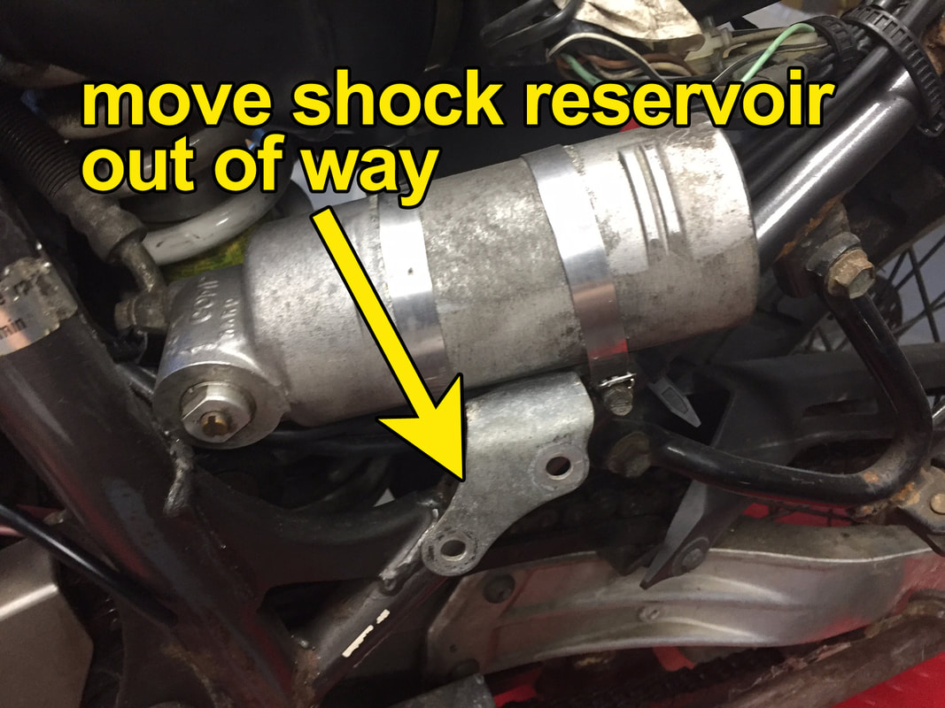
Moving the shock fluid reservoir out of the way makes it easier to remove the stock carb
|
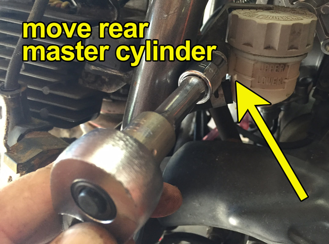
Give yourself more room on the right side of the carb by moving the rear master cylinder reservoir out of the way
|
|
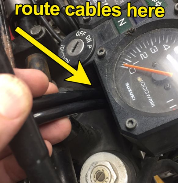
Removing the coil bolts allows room to route the throttle cables
|
|
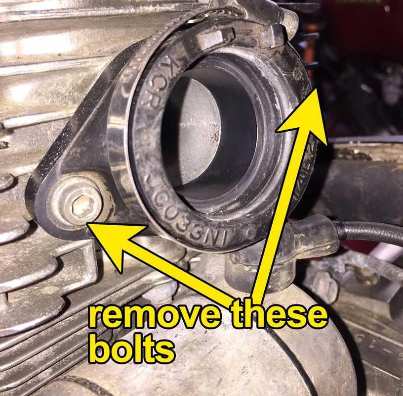
Removing the carb and manifold
|
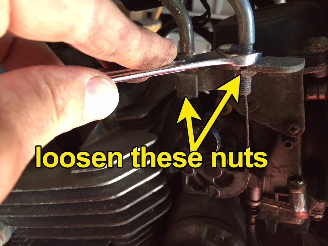
With the adjusting nuts loose, you will be able to remove the throttle cables from the carb

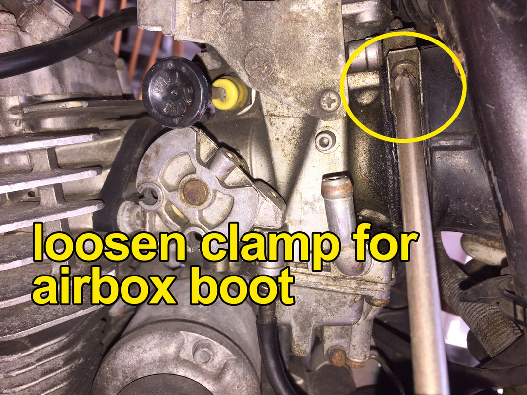
Loosening the intake manifold clamp to facilitate carb removal
|
Notes on fuel:
Because of possible fuel contamination, we always recommend you drain any existing fuel from your fuel tank before installing a new carb kit. One of the main causes of carburetor failure is contaminants in the fuel and you don't want to mess up your new carb with dirty gas. If you question whether or not your fuel is dirty, empty about a cupful from the petcock into a perfectly clean, white plastic or clear glass container. A white container is best because it allows you to easily see any sediments in the fuel. Place the container on a level surface, in a well-ventilated area and let it sit for about 30 minutes (make sure there are no nearby open flames, electrical sparks and that no one is smoking). If after 30 minutes, you can see sediment on the bottom of the container (no matter how small), you will need to change your fuel and clean your fuel tank.
A suggested method of cleaning the tank is to first empty the tank of all fuel (see notes on transferring and storing fuel below). Then put several good sized drops of Dawn dish washing detergent (it is best at breaking down oil and fuel) into the tank. Fill the tank about half way with water and vigorously swish the tank around. Empty the fuel tank and rinse it out thoroughly with a garden hose. Be sure you protect the tank from scratches by setting it on a rubber mat or thick towel. After draining the tank of all water, be sure to blow the tank dry with compressed air. The tank MUST BE completely dry before adding new, clean fuel. If you are transferring fuel into the clean tank from a fuel container, make sure the container is clean and there are no sediments floating about in the container.
The best way to transfer fuel
Transfer fuel only in a well-ventilated area. If you haven't done it already, disconnect the battery on the motorcycle. Make sure the petcock is in the 'OFF" position. Attach two to three feet of 1/4 inch hose to the barbed end of the petcock. Make sure the hose is secure and will not come off easily. If necessary, clamp the hose. The hose will be running from the petcock to a fuel container on the ground, so the length of the hose my vary depending on your particualr need. Be sure the container you are using to catch the fuel is designed to safely hold fuel. Also, make sure the container is large enough to hold all your fuel. In other words, don't use a 1-gallon container if your tank holds 2.5 gallons. Turn the petcock on and stay with the container until the tank is empty. Once empty, turn off the petcock, remove the hose and cap the continer. DO NOT SMOKE anywhere near the bike when transferring fuel or moving the container. Also, avoid any sparks while transferring fuel.
Transfer fuel only in a well-ventilated area. If you haven't done it already, disconnect the battery on the motorcycle. Make sure the petcock is in the 'OFF" position. Attach two to three feet of 1/4 inch hose to the barbed end of the petcock. Make sure the hose is secure and will not come off easily. If necessary, clamp the hose. The hose will be running from the petcock to a fuel container on the ground, so the length of the hose my vary depending on your particualr need. Be sure the container you are using to catch the fuel is designed to safely hold fuel. Also, make sure the container is large enough to hold all your fuel. In other words, don't use a 1-gallon container if your tank holds 2.5 gallons. Turn the petcock on and stay with the container until the tank is empty. Once empty, turn off the petcock, remove the hose and cap the continer. DO NOT SMOKE anywhere near the bike when transferring fuel or moving the container. Also, avoid any sparks while transferring fuel.
|
Removing the throttle cables
These procedures cover removing the stock cables and replacing them with a slightly longer cable set required for this kit. Both the old and new cable sets are push/pull-type cables. One cable pulls the throttle open with the other returns the throttle to the closed position.
|
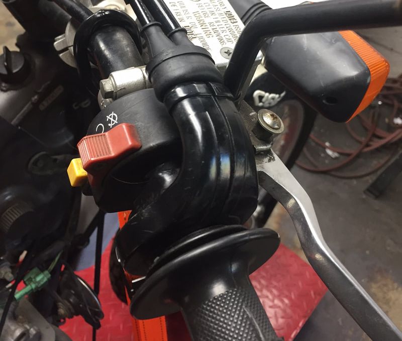
This photo shows the rubber boot rolled back at the throttle. The screws and on the base of the throttle
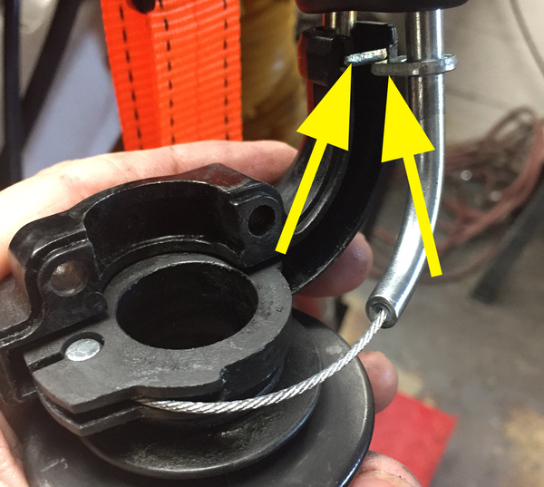
The tabs on the cables are indicated by the arrows. The round part of the tabs fit into the back of the housing with the front of one tab will face the other tab
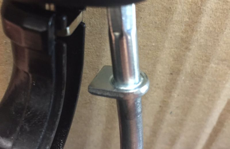
A close up of the tabs on the cable. They will only fit one way

With retaining bolts loosened, the instrument can be moved back to let the cable ends through
|
|
Upper installation of new throttle cables
|
With the boot over the cable end, route the cable set between the instrument cluster and the handle bars toward the engine

In this photo the push cable is inserted into the recess in the twist grip
In this photo the barrel end of the "pull" cable is seated in the correct recess and the halves are ready to be joined
|
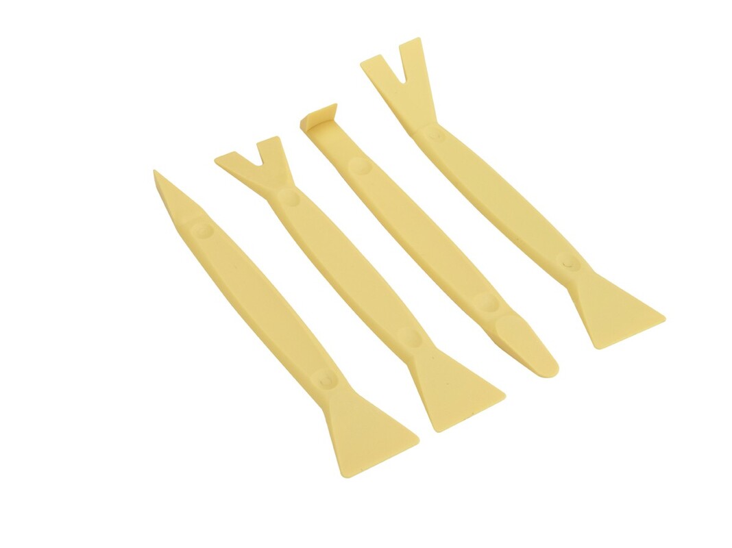 Nylon pry bar set from Harbor Freight Nylon pry bar set from Harbor Freight
Manifold and carburetor installation
|

The factory, rubber flange adapter mounted to a new TM33. Notice the rubber tangs (protrusions - shown by arrows) on opposite sides of the of a raised casting in the center of the intake bell on the TM33
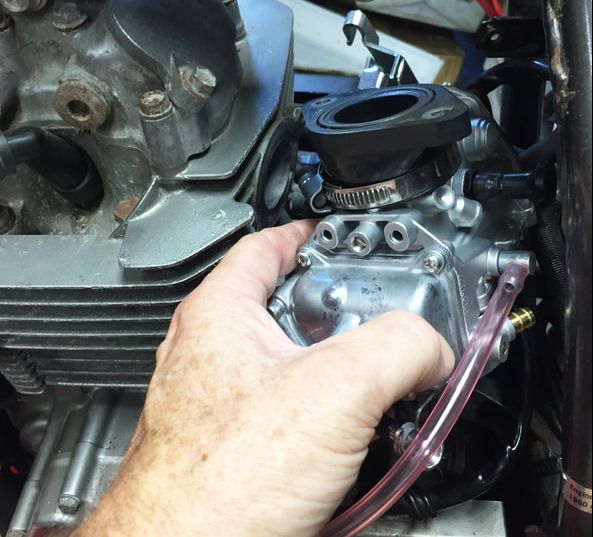
With the factory flange adapter mounted to the carb, insert the carb from the left side of the engine like shown, then rotate and turn into position
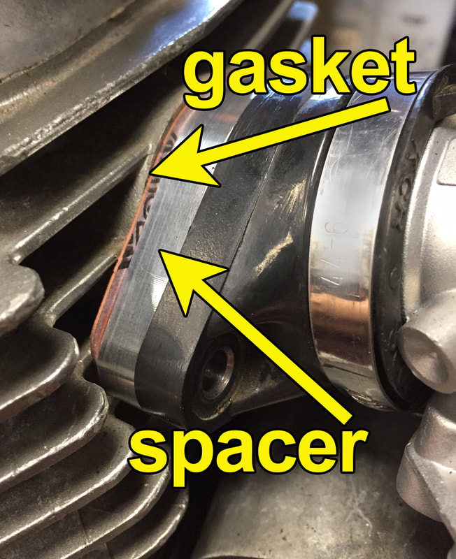
The prototype spacer shown in this photo was aluminum colored. The spacers included with our kit are now gold anodized.
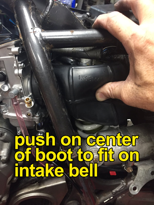
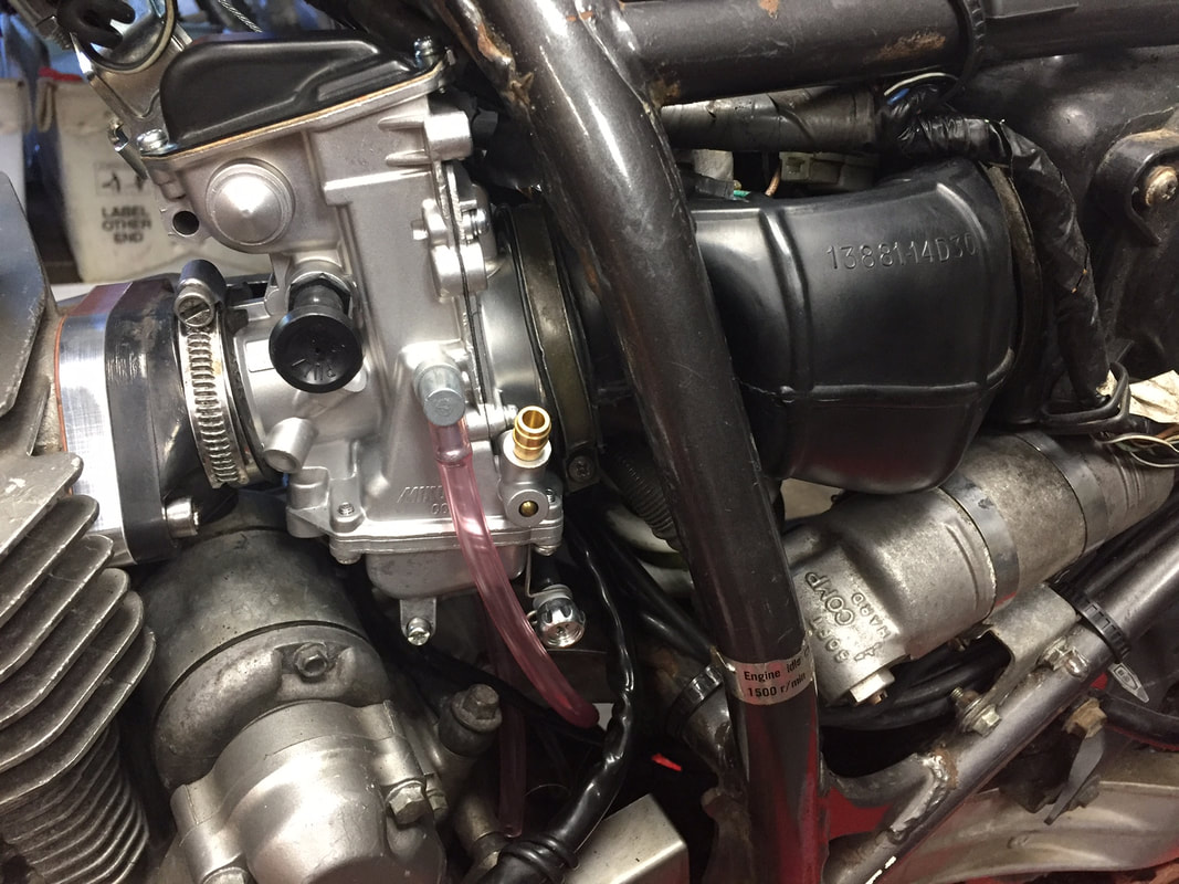
Air box boot seated properly and hose clamp in place. Avoid any gaps when seating the boot
|
|
Installing and adjusting throttle cables
|
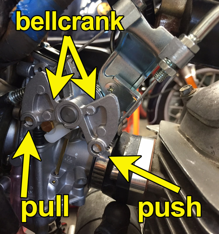
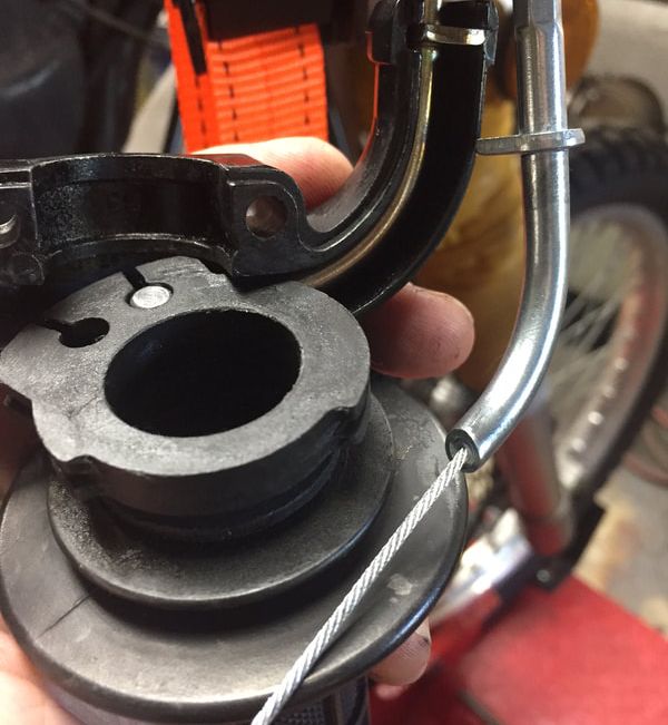
With throttles cables in place, this photo shows the location of the push and pull cables
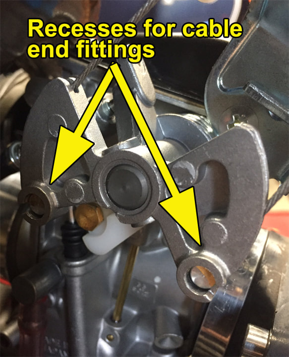
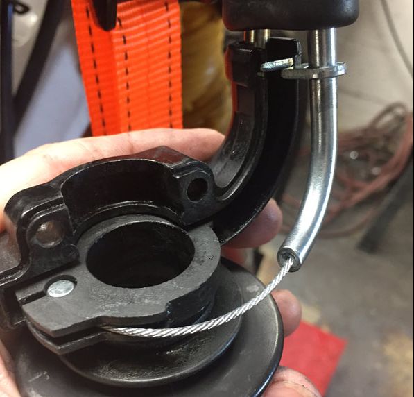
This photo shows the location of the recesses on the bellcrank where the barrel- end of the throttle cables are placed

Cables in place, but securing nuts not yet adjusted.
|
|
Completing the installation
|
A reminder about fuel: When putting on a new carb, we highly recommend cleaning your fuel tank and replacing the fuel with new, high octane fuel. After years of use, sediments can find their way to the bottom of fuel tanks and eventually into the carburetor. You don't want this to effect the performance of your new carb so make sure the gas is clean! See "Notes on fuel" above. Being imprinted on clear plastic, it's sometimes hard to see, but the arrow on the filter indicates the flow of fuel. If the filter is on backward, it won't work properly.
|
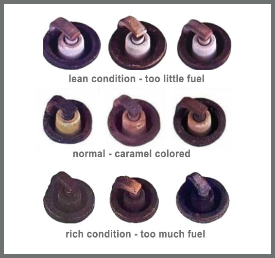 The color of the insulator can provide and excellent report on the fuel/air mixture
Initial start and tuning
You could start your bike at this point and chances are it would run okay. But if you stopped here, the bike probably wouldn’t run to its full potential. This next step doesn’t take that much time and it will ensure your bike is running properly. Tuning and jetting is individual to every motorcycle. Some bikes have more wear than others. Some may be fitted with aftermarket pistons, cams, exhaust or air cleaners. These changes effect a bike’s jetting set up. Not only should your bike idle smoothly with a new carb, you should also make sure the fuel mixture entering your intake manifold is correct for your bike. A fuel mixture that is too lean will sometimes make your bike feel like its performing better, but it can also going to run at a very high engine temperature and ruin your engine very quickly. A mixture that is too rich can sometimes protect the engine from damage, but will also make the bike run poorly. The best way to tell if your mixture is spot-on is by the color of a new spark plug after testing the bike under certain conditions for a few minutes.
Take a look at the color of the ceramic insulators in the photo to the right. The spark plugs with bright white insulators are indicating a lean condition, or not enough fuel. The dark or sooty plugs are indicating too much fuel in the mix. The plugs in the middle are a nice caramel color. They indicate the correct fuel mixture. Ideally, you want your plugs to be this color.
When we ship these carb kits, they are jetted for stock bikes ridden in an altitude range between sea level and about 3500 feet. If a bike has been modified with performance parts or if it is ridden at higher altitudes for any length of time, it will probably need jetting correction. If your bike is mostly stock (no performance cams or exhaust system) and you do most of your riding at an altitude below 3500 feet, then this kit should already be properly jetted for your bike. Keep in mind, you'll still need to adjust the idle and mixture screws.
For customers who have made performance modifications to their bikes, it's a good idea to begin testing your jetting with the jets we've already installed. Your bike will run with these jets and they will provide you with a baseline for correction. Please follow the steps below:
Checking the Jetting:
On a Mikuni round-slide carburetor, there are four ways to adjust your fuel/air mixture:
Checking the jetting at idle:
You could start your bike at this point and chances are it would run okay. But if you stopped here, the bike probably wouldn’t run to its full potential. This next step doesn’t take that much time and it will ensure your bike is running properly. Tuning and jetting is individual to every motorcycle. Some bikes have more wear than others. Some may be fitted with aftermarket pistons, cams, exhaust or air cleaners. These changes effect a bike’s jetting set up. Not only should your bike idle smoothly with a new carb, you should also make sure the fuel mixture entering your intake manifold is correct for your bike. A fuel mixture that is too lean will sometimes make your bike feel like its performing better, but it can also going to run at a very high engine temperature and ruin your engine very quickly. A mixture that is too rich can sometimes protect the engine from damage, but will also make the bike run poorly. The best way to tell if your mixture is spot-on is by the color of a new spark plug after testing the bike under certain conditions for a few minutes.
Take a look at the color of the ceramic insulators in the photo to the right. The spark plugs with bright white insulators are indicating a lean condition, or not enough fuel. The dark or sooty plugs are indicating too much fuel in the mix. The plugs in the middle are a nice caramel color. They indicate the correct fuel mixture. Ideally, you want your plugs to be this color.
When we ship these carb kits, they are jetted for stock bikes ridden in an altitude range between sea level and about 3500 feet. If a bike has been modified with performance parts or if it is ridden at higher altitudes for any length of time, it will probably need jetting correction. If your bike is mostly stock (no performance cams or exhaust system) and you do most of your riding at an altitude below 3500 feet, then this kit should already be properly jetted for your bike. Keep in mind, you'll still need to adjust the idle and mixture screws.
For customers who have made performance modifications to their bikes, it's a good idea to begin testing your jetting with the jets we've already installed. Your bike will run with these jets and they will provide you with a baseline for correction. Please follow the steps below:
- If your bike was running okay with your old spark plug, you may leave it in for the time being. If the plug is fouled (black or sooty in color, you should replace it).
- Temporarily adjust the air/mixture screw by first gently tightening the screw in all the way. Do not over-tighten this screw or you could damage the seat for the screw. Once in all the way, back the screw out 1-1/2 turns.
- Start your motorcycle. After a minute or so of warm up, let the bike settle to an idle. If it does not idle, try turning in the idle screw until the engine can maintain a smooth idle.
- With the bike at a smooth idle, slowly begin backing out the air/mixture screw. The idle should rise a bit. Continue slowing backing off the air/mixture screw until the idle peaks. When it does, turn the idle screw in ¼ turn.
Checking the Jetting:
On a Mikuni round-slide carburetor, there are four ways to adjust your fuel/air mixture:
- The pilot jet - Also known as the slow jet, this jet controls the fuel/air mixture at or just above idle. The idle mixture is further controlled by the air mixture screw mentioned above.
- The slide cutaway - The cutaway in the throttle slide begins working the moment the throttle slide is lifted. The larger the cutout on the slide, the more air that enters the fuel/air mixture.
- The needle jet and jet needle - These two items work together to control the mixture in the mid range
- The main jet - This jet controls the fuel air mix for the top 25-percent to full throttle.
Checking the jetting at idle:
- Warm up the bike and install a new spark plug (correct type recommended by the manufacturer). With the engine warm, start the bike without using the choke. Let the bike idle about five minutes. Do not rev the engine. Keep the engine at idle speed the entire time. Remember you are only checking the idle circuit and only one circuit can be checked at a time.
- Shut the bike down with the key or kill switch (do not choke to stop it) and let the engine cool for a few minutes before you remove the spark plug.
- Check the color of the insulator on the spark plug. If it’s bright white, you’re not getting enough fuel in the mixture and you’ll need a larger pilot jet. We include a larger jet with the kit. If it’s just slightly white, you can try screwing in the air mixture screw about ½ to 1 turn and run the test again with a new plug. If the plug is dark in color, you’re getting too much fuel and you’ll need to restrict the fuel flow at idle with a smaller jet. There is one included with the kit, but we sell all available sizes for this carburetor.
- Similar procedures can be preformed to check the mid-range and top end. To find out more about these procedures, please go to our Mikuni Tuning and Jetting Manual.
