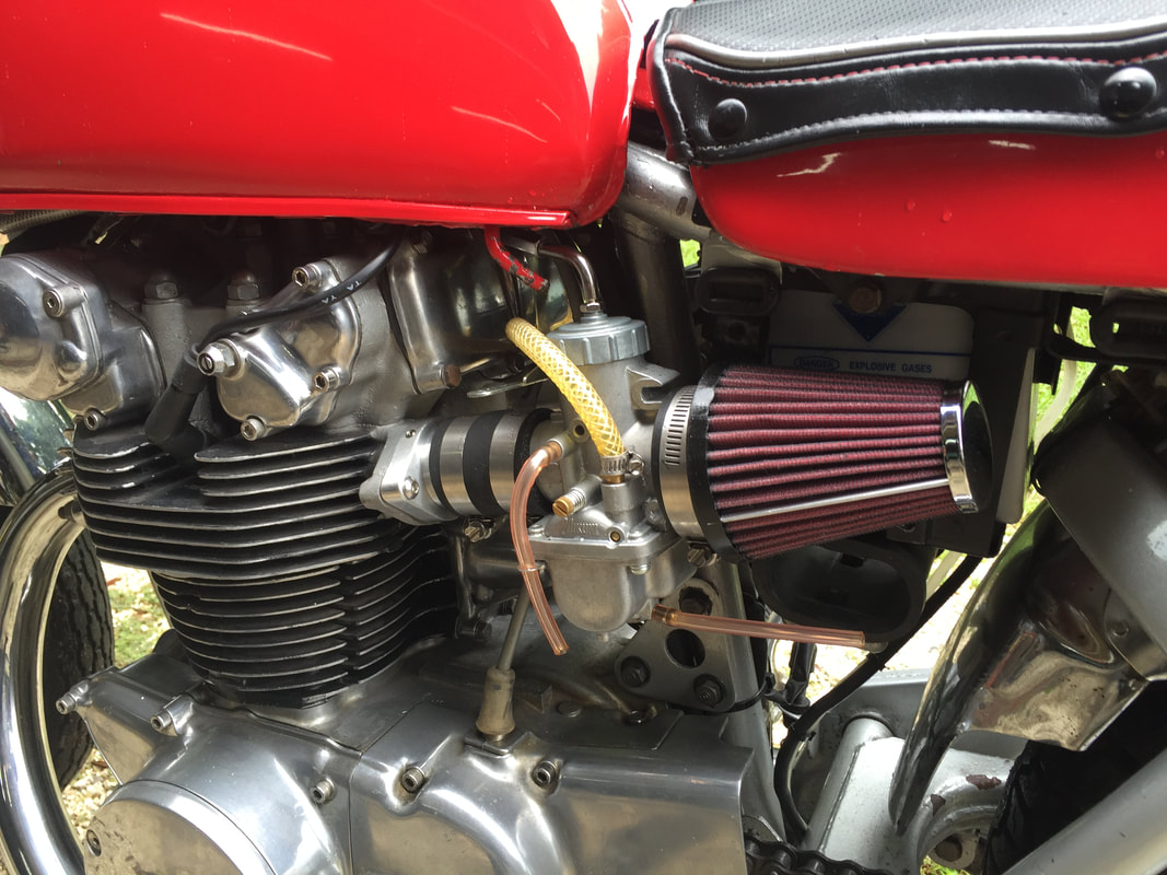
Honda CB450 – VM32 Carburetor Conversion
Installation Instructions
NOTE: This is an instruction manual I designed for my employer, Niche Cycle. These kits can be found at nichecycle.com
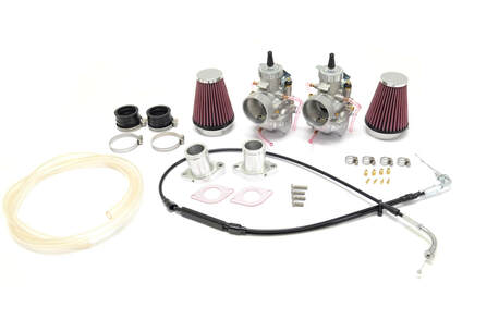 The complete Niche Cycle CB450 kit.
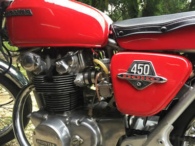
The following is a step-by-step guideline for installing the Niche Cycle 32mm Mikuni Kit on your Honda CB450. These trend-setting motorcycles were built by Honda from 1965-1975, making the survivors all over 40 years old. In most cases, a number of hands have worked on these bikes – some professional and some amateurs. There is a good possibility a number of people have worked on your bike too. You may find as you install this carb kit, some of the cables and wires may have been mounted differently from the factory position. It’s also possible some of the factory parts may have been substituted as well. With bikes that have been in circulation as long as the CB450, it’s not at all unusual to find SAE nuts and bolts on a bike that was delivered from Japan with all metric hardware. Our demonstration bike was no different.
Because of this, you might need to modify these instructions a bit to work with your bike. The most important thing is to first read through the instructions carefully. Give yourself a clean place to work and plenty of time to do the job. This is not a 30-minute project. You might want to set aside a full day or even a weekend to install this kit.
What’s included in your kit:
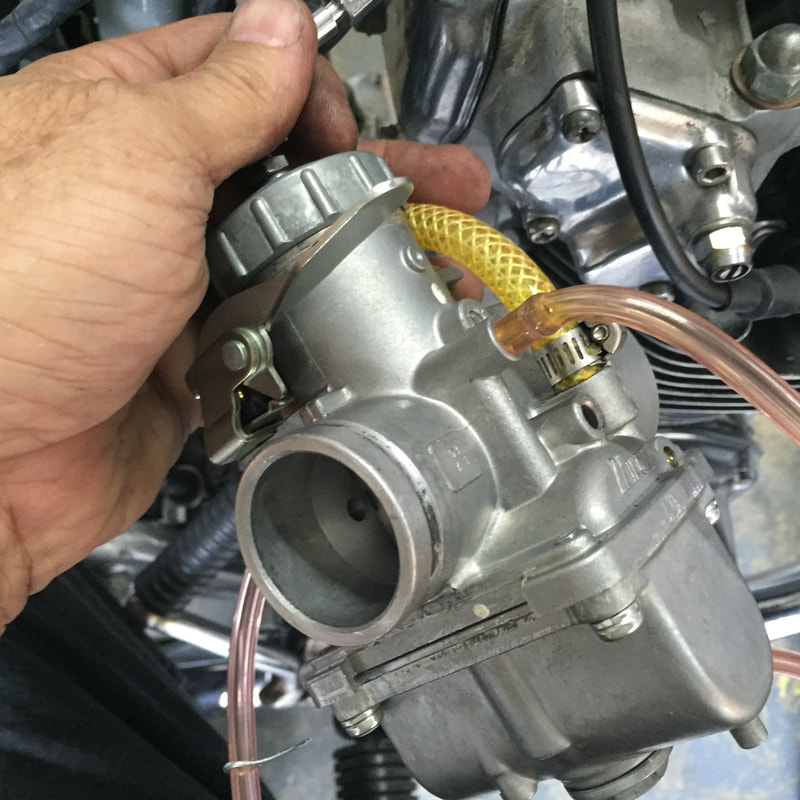
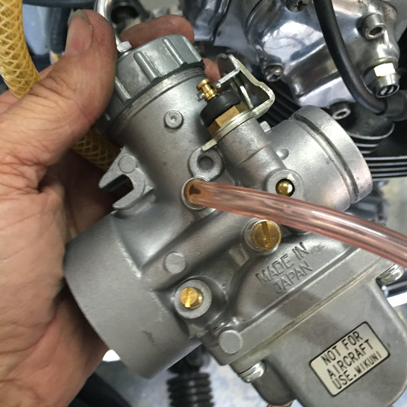
- Two Mikuni VM32 carburetors: VM32-193 (right) and VM32-33 (left). The only difference between these carburetors is the location of the idle speed screw.
- Two billet manifolds (there is a left and right with these manifolds)
- A two into one, high quality, stainless throttle cable
- Two manifold rubber adapters
- Four high quality, stainless steel clamps
- Two manifold gaskets
- Four 6mm, button head machine screws (three long, one short)
- Two braided fuel lines
- Four, stainless steel fuel line clamps
- Two pod-style air filters
- Two stainless, pod filter clamps
- Additional jet kit for tuning
Tools you’ll need
Make it easy on yourself and use the right tool for the job. If we’re very specific about a tool, it’s because using anything else will probably cost you time and money. If you don’t have the right tool, get it before you start the job. It will save you a lot of aggravation. If you try to use tools like an adjustable wrench or a vice grip in place of the right tool, you’ll round-off the nuts or bolts and then have to replace them. With metric tools so cheap and available on Amazon, eBay or Harbor Freight, it’s just penny wise and pound foolish not to get the right tool for the project.
One of the best tools you can use is a cell phone or digital tablet. Professional mechanics used to draw a lot of diagrams, but these days, they take lots of pictures when taking something apart – especially something they are unfamiliar with. Some also use a spiral bound notebook to take notes. You’ll find any notes and pictures you have could save a lot time and frustration on a project.
If you own a motorcycle, you may already have all of the tools listed below to maintain your bike. Rather than list individual sockets or wrenches, we’ve noted them as kits, because that’s how they are normally sold. You won’t need all the wrenches or sockets in these kits, but it makes more sense to buy the kit than buying these tools individually. Here is a list of tools and items you will need:
- A flat blade screwdriver set
- An 10-12” long #2 flat blade is needed for air screw adjustment and may not be in kit
- A Phillips-head screwdriver set
- Metric Hex Key (Allen wrench) set
- Metric combination wrench set (6mm-19mm)
- Metric socket set (6mm-19mm)
- Razor knife (for cutting hose)
- Pliers (regular and needle nose)
|
Disassembly process: This disassembly process is very straight forward and requires no advanced mechanical knowledge. If you find you are having trouble with these steps, you may want to look into having a professional install your carb kit.
|
Safety Note: Do not smoke or create any sparks while draining fuel from the fuel tank. Only use a container designed for holding fuel. Do not draing the tank with the engine hot. Drain the tank in a well-ventilated area. Do note leave the bike unattended while draining fuel. |
Removing the fuel tank
- Remove the right side cover and disconnect the negative terminal of the battery.
- Remove the left side cover (be sure to label and keep track of all hardware). Baggies are great for this.
- Turn the left and right petcocks off on your fuel tank.
- Remove the old fuel line from the petcocks.
- Run a spare piece of fuel line from one of the petcocks to a fuel container capable of holding the contents of the tank (5 gallons will work).
- Drain the fuel tank into the fuel container. Be sure to put the petcock on reserve and do your best to completely empty the tank.
- Once tank is drained, place an absorbent rag under the fuel tank. Remove the rubber crossover tube which is underneath the tank. If this had not been removed in a long time, you will want to replace it with a new one, so go ahead and take it off. This will make the job easier. There is almost always some residual fuel left in the tank after draining. The rag is to catch that fuel.
- If you have a stock seat, open the seat and use a bungee cord to keep the seat open (as wide as possible) Remove the rear retaining bolt and washer on the fuel tank. Lift the back of the tank up slightly and then carefully pull it backwards. Be careful not to scratch the tank on the edge of the seat. It’s a good idea to place a soft towel over the tank to keep it from being scratched by the corner of the seat. If you’re really concerned about the paint on your tank, I suggest you cover the tank with a towel and remove the seat completely before removing the tank.
- Remove the two round tank rubbers from the frame near the gooseneck, place them in a baggie and label them for reassembly.
- Using an 8mm or 10mm socket and ratchet (varies depending on year), remove the retaining bolt from the center of the side cover and remove the cover. With the side cover removed, the plastic air box cover on the left side will pull away from the air filter assembly. Remove the clamp securing the air box connector to the carburetor. Using a 10mm wrench or socket, remove the bolts from the top corner of the left air filter. Now you may remove the factory air cleaner on the left side.
- Repeat the procedure on the right side. Once removed, the factory air cleaners may be set aside.
- Loosen the clamp on the rubber intake manifold adapter on the left carburetor.
- Loosen the throttle cable adjuster locking nut. This is located at the end of the outer sheath of the throttle cable between the stock Kehin carbs. To do this you’ll need an 8mm or 10mm wrench (depending on whether or not it’s a stock cable). Unscrew the cable adjusters from the bracket and then swing the cable to the side of the left carburetor. Remove the barrel end of the throttle cable from the bellcrank on inside of the carburetor.
- There is a pinch nut and bolt that attaches the choke rod to the carburetor. This rod looks like a flat, flexible, metal band situated between the carburetors. This device synchronizes the choke valve on the stock carbs. Once the bolt has been loosened and removed, slide the end of the choke rod off the left carburetor.
- Pull the left carburetor back slightly to remove it from the manifold adapter and set it aside.
- Remove the right throttle cable and carburetor using the process in steps 1-4. You can keep the choke rod attached to the right carburetor.
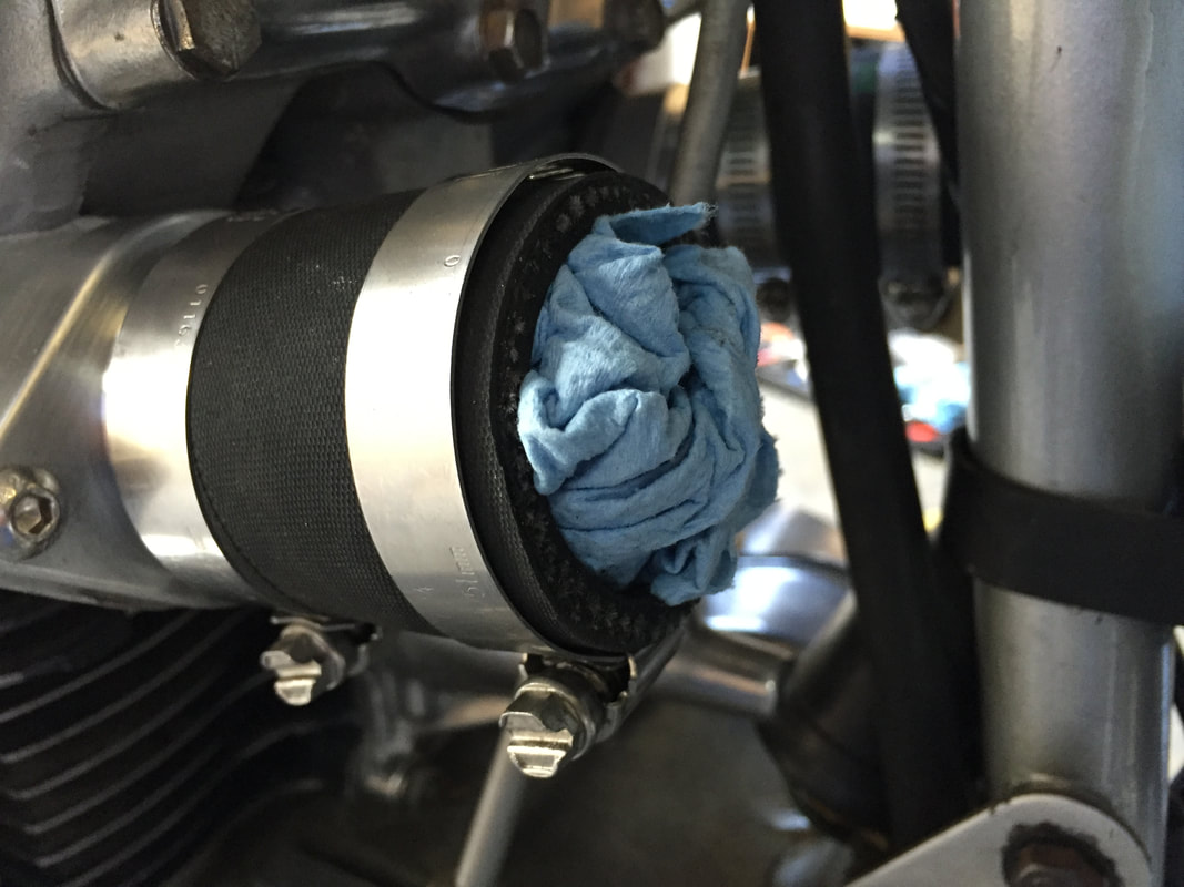
- Place a small shop rag in both of the intake manifolds. This will protect you from having to disassemble the engine if you were to drop any hardware into the manifold.
- Using a 10mm wrench, remove the four, 6mm bolts and lock washers securing the stock intake manifolds. If the manifolds do not lift off easily, get a small block of wood, place it against the side of the manifold and tap it gently with a small hammer until it breaks loose. Carefully stuff small rags into the cylinder head where the manifolds bolt up. This will keep hardware and debris from falling into the manifolds during the following processes.
- Using a 14 or 13mm wrench (depending on the cable) and loosen the lock nut on the 90-degree bend of the throttle cable where it attaches to the twist throttle handlebar assembly.
- Loosen the two Phillips pan-head screws holding the halves of the throttle housing together. Carefully separate the halves, taking care not to break the starter button wire. Remove the throttle cable barrel end from the plastic throttle grip. Remove the grip section from the handlebar. Rotating the cable counterclockwise, remove the elbow from the housing and draw the end of the inner cable though the housing.
- Remove any wire-ties or cable clamps attaching the throttle cable to the frame and remove the existing throttle cable. If the cables have been routed between the motor mount at the top of the cylinder head, you will need to loosen the four bolts using a 13mm combination wrench and socket.
Tip: Don't throw those old parts away!
Even if you're sure you never want to use those old Kehins carbs anymore, they still have value to restorers who need original parts. You can put them on eBay at a reasonable price and be sure to sell them. If your bike is all original or fairly close to to original condition, you might just want to put the parts in a box and hold onto them. The next owner might be looking for an original bike and those old parts may raise the value.
A great way to store your parts is to label and bag everything and place it in a box. You might need to reference them later. We highly suggest draining the fuel from the old carburetors so they aren’t a fire hazard. This will also keep the old gas from smelling up your garage in a few months.
Assembly Process:
Manifold Installation:
Manifold Installation:
|
Caution: To avoid damage to your cylinder head, never use a chisel, screwdriver blade or any hard steel tool to clean the mating surface for the manifold. These tools could put a deep gouge on the surface which could ruin the cylinder head. These surfaces can be cleaned using a hard plastic scraper or the flat side of a razor blade. |
Cleaning your manifold surfaces It's best to remove gasket remains from cylinder heads using a hard plastic paint scraper but for those really stubborn pieces, you might need an industrial, rectangular razor blade. To remove the sediments, spray a little brake cleaner on the manifold surface, then hold the blade flat and nearly parallel to the surface of the manifold mating surface of the cylinder head. Gently scrape off any remnants of the old paper intake gasket. Keep in mind that these razor blades are made of steel and are harder than aluminum. So be extremely careful not to gouge the soft aluminum mating surface on the cylinder head. With the sediments gone, clean the surface with denatured alcohol or non-chlorinated brake clean. |
- If you have not done it yet, place a balled up paper towel or small rag in the intake opening on the cylinder head. Place it just below the surface of the manifold. The surface of the intake manifold on the cylinder head must be perfectly clean. Of course, the new manifold we'll be shipping to you will be. But, more often than not, the old paper gaskets leave sediments on the manifold surface when removed. If these old pieces are not removed, air leaks can ensue, which will make the bike run lean (if at all) and running lean can quickly ruin your engine. So you want this surface on the cylinder head perfectly clean before you install the new manifolds.
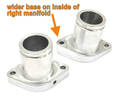
- Carefully remove the balled up paper towel or rag in the left intake port only. Take care that no gasket debris falls into the cylinder. If some does, use a small vacuum cleaner to remove the debris. Gather together the left manifold (the one with the flat base), one manifold gasket and two of the shorter, button-head screws. Place the intake gaskets under the new intake manifold and mount it to the left cylinder. Do not use any gasket sealing compound. If both surfaces are clean, a gasket sealer is not necessary. Tighten the screws evenly using an Allen wrench, hex key or socket (depending on the type of manifold bolt used). Do not tighten one side fully then the other. Go back and forth until evenly tightened. Use caution because stainless steel screws are soft and can be easily broken. Do not over-tighten. NOTE: On the top side of each manifold is a set screw which can be replaced with an adapter for a vacuum synchronizer. Make sure this screw faces upward when installing the manifolds.
- With the left manifold in place, follow the same procedure for the right manifold. Be sure to note that the base of right-side manifold (where it bolts to the head) is specially designed to have the inside portion of the manifold (the side closest to the left carb) thicker than the outside (where it bolts to the head). This angles the manifold outward so the right-hand carb will not make contact with the frame. Be sure the screw for the vacuum tap is facing up. You will find that the longer manifold mounting screw fit the thicker side of the manifold in the inner bolt hole of the right manifold.
- Slide the rubber manifold adapters into place over the ends of each of the manifolds. Place two hose clamps over each adapter. Make sure the screws on the clamps are on the bottom and facing you. Tighten the clamps closest to the cylinder head. Once the manifold is in place, put another CLEAN balled up paper towel or shop rag in the manifolds. This will keep you from accidentally dropping any screws or debris down the manifold while waiting to install the carbs.
Fixing scratches or gouges in the manifold surface
If you find there are scratches or gouges on the manifold surface, depending on how deep they are, you may be able to remove them by following this procedure:
If you find there are scratches or gouges on the manifold surface, depending on how deep they are, you may be able to remove them by following this procedure:
- First make sure you have a paper towel or rag stuffed into intake.
- Then take a small, flat block of wood, metal or hard rubber (about 4” x 3”) and wrap some 400-grit wet/dry sand paper around the block.
- Spray the sandpaper with WD-40. While keeping the block level to the surface, move it back and forth, up and down until the scratches are removed. The block is absolutely necessary and must be used to keep the manifold surface perfectly flat. Manifold air leaks can be caused by surfaces that are uneven.
- Once the surface is free of debris and scratches, use denatured alcohol (spray brake cleaner products work well too) and a clean cloth to wipe the surface of the manifold flange.
- Use a vacuum cleaner to suck out any debris that might be on top of the rags in the manifold. This will keep the debris from falling in when you pull the rags or paper towels out.
Throttle cable installation
Routing the cable to the handlebar
Routing the cable to the handlebar
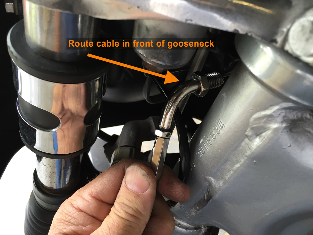
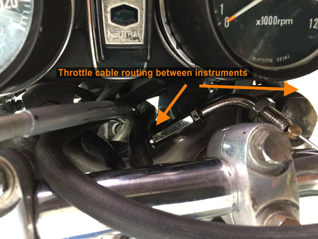
- Before you attach the throttle cable to the carburetors, route the upper, single section of the throttle cable up towards the goose neck, between the instruments and over the handle bar to the twist throttle. Make absolutely sure there are no hard bends in the cable or that nothing pinches the cable. Turn the handlebars fully to the left and right to make sure there is plenty of clearance for the cable.
- If you put the two screws back in the throttle assembly to keep them from getting lost you should now remove them so the twist throttle assembly halves can be separated. (see step 2 of Removing the throttle cable in the disassembly process). NOTE: Handle the lower throttle housing with great care, especially if the wiring is original. It is very easy to pull off the small wire that runs to the electric start button. If this wire is detached, it will need to be re-soldered.
- Temporarily pull about 6 inches more cable than you need toward the end of the twist throttle housing. This will give you a little more scope in the cable to work with and make screwing the elbow into the housing easier.
- Feed the end of the throttle cable, up through the hole in the bottom of the twist-throttle housing. The 90-degree elbow will be screwed into this threaded socket.
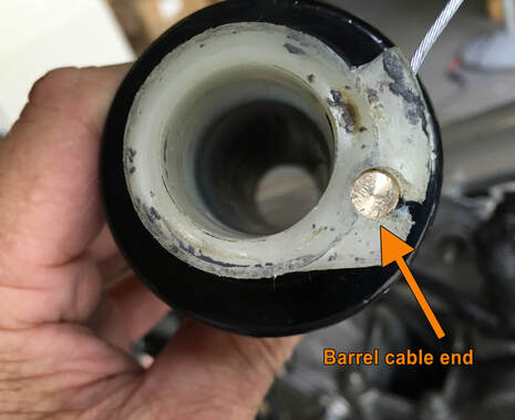
Attaching cable to twist throttle
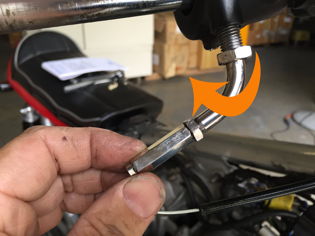
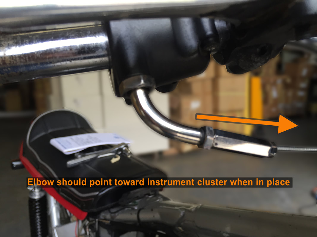
- Carefully rotate the end of the chrome, 90-degree elbow clockwise around the housing screwing it in (photo above left). You might have to back off a half a turn or so to make sure the cable end is facing the instruments.
- Using a 14mm wrench, secure the lock nut on the elbow which should face the entry point of the cable near the instruments. Keep in mind that you don’t want any sharp bends on the cable.
- Place the barrel end of the cable into the slot on the plastic throttle grip (see photo lower left). Gently pull on the carburetor end of the cable to eliminate any slack. Fit the grip inside the housing. Check for freedom of movement and close the halves of the housing. Carefully tighten the screws. Make absolutely sure no wires are being pinched and the twist grip has free movement. After the screws have been secured in the throttle assembly, it’s a good idea to have an assistant hold tension on the end of the cable while you check the throttle cable to make sure it moves easily and smoothly. You should exercise the cable in and out several times to check for freedom of movement.
Routing cables to carburetors
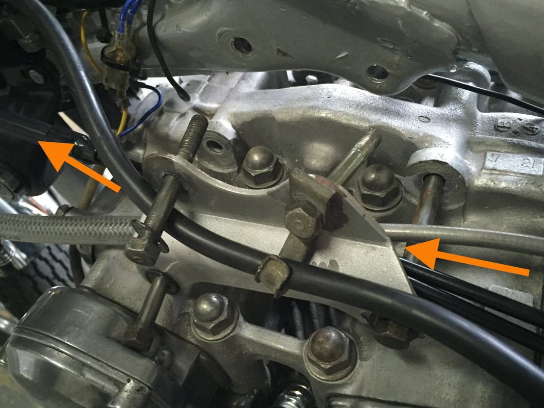
- With the single upper cable in place, we will now turn our attention to the lower cables. Just before the cylinder head mount bracket, the cable will split into individual cables for each carburetor. The two cables should be routed under this bracket. To do this, the four bolts for the bracket must be loosened. The throttle cables will run under the frame next to the cylinder head, between the left cylinder head engine mount (picture above left). It is important that there is no slack between the top of the carburetors and the motor mount. Take up any slack near the neck of the frame. Do not tighten the frame mounts until the carbs are fitted. Take care not to pinch the cable between the frame and mount. You will see that near the bottom of the mount there is space for the cable to move freely.
- Identify the VM32-33 (left side) carburetor. The left side carb will have the idle set screw located on the left side. Unscrew the top cap. Remove the spring, slide and needle, then place all the parts in a labeled container or baggie where the parts won’t get lost or dirty (see photo below showing left side carb). Do the same with the right side carb. Label the bags so parts are not confused. While they may look identical, the slides are different and paired to each carburetor.
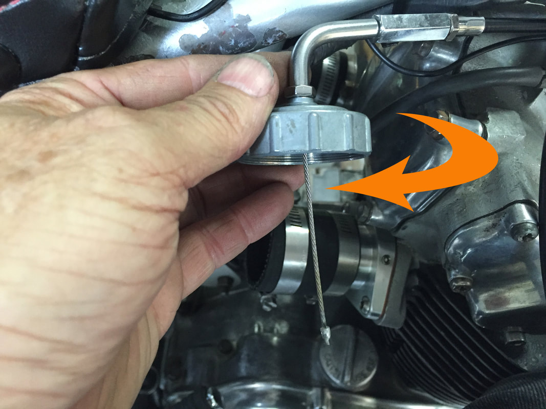
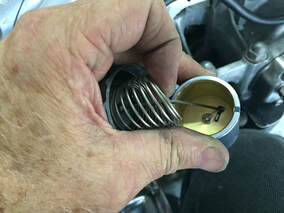
- Remove the carburetor cap from the bag of left carb parts. Insert the closest cable end through the center of the cap and screw the end of the 90-degree elbow onto the cap (center picture above). Pull on the throttle end of the cable, taking up any slack. Check to make sure all the cable junctions are settled inside their cable-end fittings.
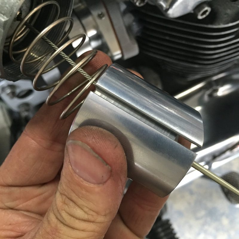
- Place the throttle spring up against the top of the carburetor cap with the cable running down the center of the spring (top right photo). Make sure the round spring seat plate is removed from the bottom of the slide and that the needle is in place in the center of the slide. Push the brass fitting on the end of the cable through the bottom of the large hole in the slide. Move it across the slot into the small hole. Flip the slide upside down and make sure the cable is bottomed out in the recess under the small hole.
- Set the spring seat plate in the slide, while making sure the notch faces downward in the slot between the two holes. The plate must be flat to secure both the needle and the throttle cable. Release the spring into the slide and place the slide into the mixing chamber of the carburetor (see photo below left).
- Route the assembled left throttle cable with the cap, spring and slide to the left side of the engine.
- Duplicate steps 3-5 with the right carb and route this assembled cable and slide to the right side of the engine.
- NOTE: The spring seat plate has about ¼ of the area notched away and there is a tab that is bent away from the flat side of the plate. That tab faces down and is used to keep the throttle cable in place. Also, please note that there are two holes in the plate. The one in the center goes over the top of the needle. The other hole is not used. With the end of the cable in place, the plate must sit flat with the notch in the slot between the two holes and the center hole over the top of the needle.
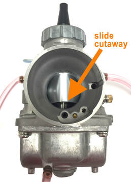
- NOTE: The slide can only be placed in the carburetor in one direction. If you examine the slide you will notice that there are two grooves cut into the slide: a long thin groove that runs the length of the slide and a shorter, fatter notch that is cut into the opposite side. If you look down the cavity where the throttle slide is placed (the mixing chamber), you will notice a small steel pin on one side and the pointed end of the idle adjusting screw on the opposite side. The long groove must line up with the small steel pin. If you think you may have confused the slides, remember the slide cutaway must fact the rear (intake side of the carb).
Fitting slides to the carbs
- Once again, identify the VM32-33 (left side) carburetor. This carb will have the idle set screw located on the left side (see photo above left).
- If you have it in place, remove the rag or ball of paper from the rubber adapter.
- Take the left carburetor, and insert the left slide into the carb body. Keep in mind, the slide will only fit in one way and it is possible to swap the left slide for the right. So, when the slide is fully inserted, check to be sure the slide cutaway is visible at the rear (intake ) side of the the carb.
- With the slide in place, compress the spring and fit the cap to the carb body. Because of the type of cable end used, you will not be able to simply screw on the mixing chamber cap onto the throttle body without unscrewing the elbow on the cable. So you will need to rotate the carburetor around the cap until the cap is snug (see photos below). When the cap is secured, rotate the 90-degree elbow forward and tighten the lock nut at the base of the elbow.
- Repeat this process for the right side carb.
|
The importance of syncing carbs
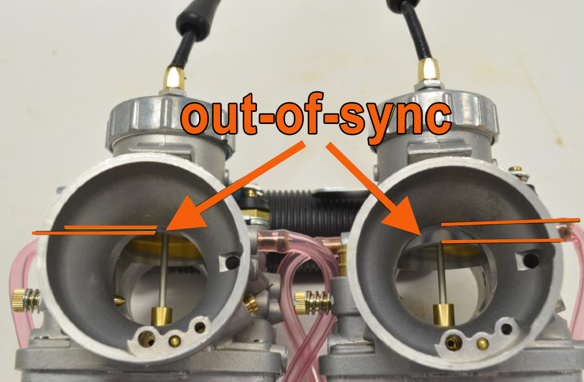
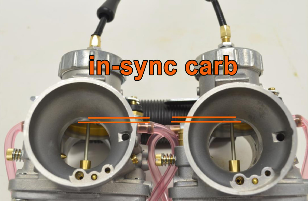
Static syncing is the process where you adjust the length of the throttle cable to make sure the throttle slides lift at exactly the same time. The goal with static balancing is to ensure that all cylinders are receiving an identical fuel/air mix at the exact same time. The goal with static balancing is to ensure that all cylinders are receiving an identical fuel/air mix at the exact same time. You can also dynamically sync the cylinders with a vacuum calibration tool once the bike is running, but you still need to statically sync the carbs first. A multi-cylinder motorcycle is essentially multiple engines sharing the same crankshaft. If one of those engines isn't running at the exact same speed as the other, performance will suffer greatly. Yes, it will run, but it won't run right. Customers are often shocked at how different the bike runs when the carbs are properly synced. If a carb is out of sync, performance will certainly be diminished, but the bigger issue is the potential damage that can be done to the engine. So, this is not a step you can short cut. |
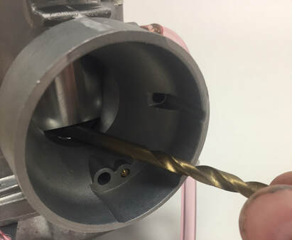 Using the smooth end of a drill bit to gauge to set the idle identically in both carbs.
Setting the idle
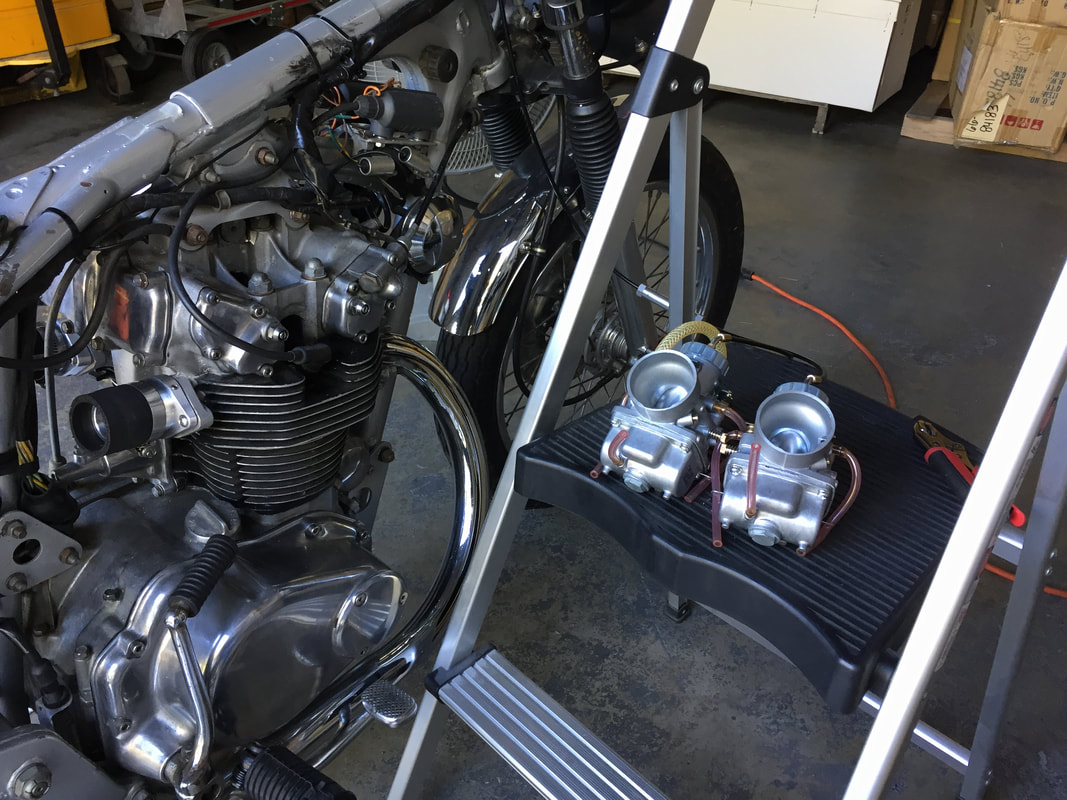
- Find a place where you can rest the carbs against the engine or foot pegs with the intake side of the carb facing up. If this isn't possible, you may want to rest the carbs on a box or foot stool so they can as close as possible to the bike but still allowing a full view of the throttle slide while looking over the bike. Be sure that the throttle cables are free and there is no tension on the cables. If the cables are tight, it may pull up the slide slightly which would keep you from successfully syncing the carbs.
- With the the throttle closed, there should be just the slightest amount of play (about 1mm) in the cable. Use the cable adjusters to set the correct amount of play.
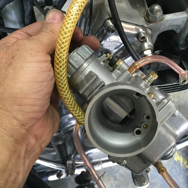
- Looking down the intake of the carb, you’ll notice the base of the throttle slide has an arched cutout at the bottom. This is the cutout. The idle adjustment screw on the side of the carb mechanically raises the throttle slide in very small increments. As you turn the screw clockwise, the end of the screw slides further under the skirt of the throttle slide pushing it up and increasing the fuel/air mixture to the engine - increasing the idle speed. To set the idle (height of the slide) identically between the two carbs, you will need to come up with some kind of inflexible gauge that you can easily move from one carb to the next. This will allow you to easily judge the height of the throttle slide. One easy way to do this is to pull out a box of drill bits (aka drill index). If you look at the drill bits in an index, you'll see they increase slightly in size from the smallest to the largest. That makes them perfect for this purpose. Make sure you use the smooth shaft of the drill bit and not the cutting edge.
- Make sure your throttle slide is at the very bottom of the slide passage in both carburetors. To do this, you must back off the idle screw until turning it has no effect on the slide. Watch the slide as you turn the screw counterclockwise. You should see the slide drop just a bit. If not, turn the screw in the opposite direction until you see the slide move up, then stop and turn the screw in the opposite direction bringing the slide down a bit. Do this until the slide stops moving. The goal is for the slide to be just barely touching the bottom of the carburetor venturi.
- With the slide all the way down, find a drill bit that just barely slides under the throttle slide cutout, without lifting up the slide. You want to use the shank or smooth end of the bit, not the cutting edge. Now, swap out that bit for the next larger size. It should lift the slide up just slightly. If not, grab the next biggest size. One of those bits will typically be enough for the bike to idle. Be sure the drill bit is at a 90-degree angle to the slide - in other words, directly in front of the slide. If you hold it off to one side or the other of the cutout, it will change how much the slide is lifted. Make sure you use the same procedure with the other carb. Now, with the drill bit still holding up the slide, turn the idle adjustment screw clockwise (righty-tighty) to raise the slide just enough to release the drill bit. If you make the bit too lose, just loosen the screw a bit (turning counterclockwise) until the slide starts to make contact with the bit again. Then, tighten the idle screw again until it lifts the slide just a hair. This is usually between 1/4 and 1/2 of a turn. With your carb height set, use the same technique to set the idle on the other carb. If you find the bike idles too low, you can either go up to the next size drill bit and repeat the process above, or adjust the idle by turning the idle screw on both carbs the exact same amount (clockwise). For example, if you increase the idle on one carb by turning it exactly 1/4 turn clockwise, then do the same to the other. You can also make small, incremental turns to lower the idle as well.
Syncing carbs off the bike
Here’s a hint that might prove to be really helpful for someone syncing carbs for the first time:
Depending on the type of throttle you have, you may be able to sync the carbs off the bike. This is a lot easier because you can look directly down the bell of the carburetor to see what you are doing, unimpaired by frame tubes, battery boxes or air cleaners. This process is called bench syncing. This can be done by removing the throttle and carbs from the bike and then making adjustments remotely on a work bench. For motorcycles that incorporate electrical switches into their throttle assembly, this process isn't worth the extra effort. That's because you will have to disconnect a half a dozen or more wires from the wiring harness. You might also have to open up the headlight shell or take off the fuel tank to disconnect wires. It would certainly take more time and trouble than just syncing the carbs on the bike.
Static Syncing the Carbs
With the idle settings matched on both carbs you can now move to syncing the movement of the slides. This is done by adjusting the length of one carb cable of until both are perfectly matched.
With the idle settings matched on both carbs you can now move to syncing the movement of the slides. This is done by adjusting the length of one carb cable of until both are perfectly matched.
- With the carbs positioned on either side of the bike (see Step 1, Setting the Idle), open the throttle slowly until you observe the top of the cutaway in one of the slides just meet the edge of the intake bell on one of the carbs. This will be the point where one of the slides is no longer visible. If you open your throttle fully and neither carburetor's throttle slide reaches the top of the intake bell, then you have too much free-play in your cable and you'll have to adjust your throttle cables as needed. Note: It doesn't happen often, but every once in a while, the slides will match without any adjustment, but this is extremely rare. Normally you will observe once slide is slightly lower than the other. This is the slide you will make the adjustment to. If the slides appear to be matched, open and close the throttle several times to check. If you find this is the case with your carbs, drop everything and go by lottery tickets!
- Release the throttle. On the carb that is lower, open the mid-cable adjuster (turning counterclockwise) to lengthen the adjuster and bring up the slide up.
- Open and close the throttle again, slowing bringing the top of the cutaway in the throttle slide up to the edge of the intake bell. If the slide you previously adjusted is still too low, you can lengthen the adjuster a few more turns. Conversely, if you lengthened it too much, you can turn the adjuster clockwise to close the throttle, which will shorten the cable and lower the slide. Again, it is best to make the adjustments to one carb so your don't end up chasing your tail. It's not likely, but if you need to, you can also lengthen the cable by unscrewing the elbow some from the top of mixing chamber cap. Note: If you are working on a bike where the carbs are already mounted, you can frequently use touch to tell which slide is lower and when the slides are matched.
- When both slides are matched. Tighten the lock nut on the adjuster(s) and open and close the throttle several more times to ensure sure there is no movement in the position of the slides. If nothing has moved, you're ready to mount the carbs.
Mounting the Carbs
- With the carburetors have been successfully synced, ensure the throttle cable is properly routed under the engine mounts for the cylinder head (see Routing cables to carburetors, Step 1).
- Remove any rag or paper towel that might still be protecting the intake manifolds from debris.
- Make sure both hose clamps are in place on the adapter - one for securing the rubber adapter to the manifold and one to secure the rubber adapter to the carburetor. After that, place the intake spigot of the left carb firmly against the rubber adapter and push the carburetor into place on the rubber adapter.
- Tighten the hose clamp securing the carb to the rubber adapter and also check to be sure the clamp securing the adapter to the manifold is tight as well.
- Repeat the process on the right carburetor.
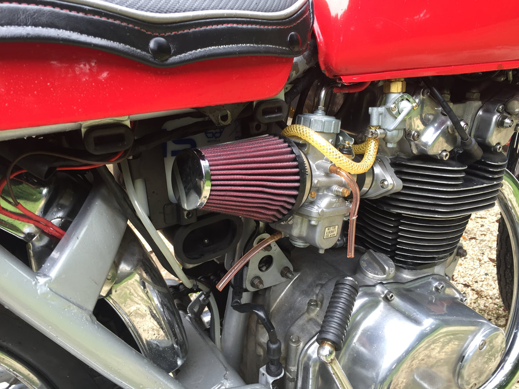
- Using the remaining two hose clamps, install the pod air filters included with the kit. Place the filters over the intake bell of each of the carburetor. Secure the air cleaner by tightening the hose clamps.
- There is not a lot of extra room between the tank and the tops of the carbs and throttle cables. Keeping that in mind, carefully replace the fuel tank being cautious not to push the bottom of the tank down onto the carbs.
- Before securing tank, check for clearance (at the top of the carbs) with the cross over tube and petcock.
- NOTE: It is possible that on bike bikes, adjustments will have to be made to achieve enough clearance for the throttle cables and carbs. Many of these vintage Honda's have been customized with fuel tanks off different model years or different makes. In addition, there have been changes to fuel tanks and many of the crossover tubes have been bent by careless handling. Additionally, rubber mountings for the tanks wear out and flatten. We have no way to account for these changes on all bikes. It should be noted that other than the black outer sheath of the cable, no other part of the carburetor should make contact with the fuel tank or frame. If it does, you will need to modify it slightly so these parts do not make contact. If you find you are having a difficult time with your crossover line interfering with the fuel line there are several adjustments you can make to resolve this issue. You may use one or a combination of these fixes to create more clearance:
- Loosen the lock nut on the throttle cable elbow (on the mixing chamber cap) and turn the elbow at the top a few degrees to clear the crossover tube.
- Raise the back of the fuel tank by adding a small piece of flat rubber to the pad under the tank. Or conversely, lower the tank by grinding off some of the rubber from the pad.
- Depending on the type of seat you are using, you may be able to shift the tank back or forward slightly to clear the cables. If this works, you will have to add to or take away from the front rubber mounts to keep the tank in place. You might also have to fabricate additional rubber mounts at the rear of the tank to keep it from rubbing on the metal frame.
- The crossover down tubes can be bent slightly for clearance. This must be done with extreme care or you will break off or crush the tube. Taking care not to break off or crush the end, grasp the crossover with a small vice grip and bend it slightly to accommodate the cable.
- Remove the crossover tube. This should only be done as a last resort. If the crossover is removed, you will need to refill your tank more often, because it will run out of fuel before it gets to the reserve point on the petcock. Many racers and customizers do this to make it easy to quickly remove the tank. It will also be necessary to seal the ends of the tubes with epoxy or a tank liner like POR-15 fuel tank sealer. If you are doing this, most of the ends of the tubes can be cut off eliminating any clearance problem
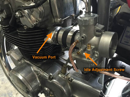
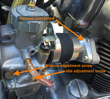
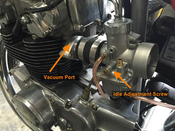 This photo shows the location of the idle adjustment screw. Do not confuse this with the smaller mixture screw
Initial Start Up
Adjusting the mixture screw
The mixture screw (also referred to as the air-mixture screw, fuel-mixture screw, idle-mixture screw or pilot screw) works in concert with the pilot jet. The mixture screw is used to adjust the fuel mixture at idle. This screw has no effect on the mid-range or top-end mixture settings. It is important to have this screw adjusted properly or the bike may run rich or lean at idle.
If a carburetor has this mixture adjustment screw located closer to the air intake side of the carb (air cleaner side), this will normally be referred to as the air-mixture screw. If the screw is located nearer to the spigot or flange mount side of the carb (nearest to the engine), then it is called a fuel-mixture screw.
During the initial start up, if you find the bike is able to idle, then you're pretty close on your pilot jet setting. You should at this time go ahead and adjust the mixture screw.
Dual Cylinder (Dead Cylinder Method)
Tuning and jetting
We ship our carb kits pre-jetted for a stock CB450 at sea level. If you typically ride at altitudes much higher than 3500’ MSL, then you might need some re-jetting to obtain optimal performance. Additionally, if your bike has performance modifications, like street-race cams, a big bore kit or a less restrictive exhaust, you might need to make some jetting adjustments.
Please see our Mikuni Tuning and Jetting Guide for more information on tuning and jetting these carbs.
- Turn on the fuel at the petcock and check for leaks. Don’t attempt to start the bike if there is a fuel leak. Resolve any leak issues and clean up any leaked fuel before attempting to start the bike.
- Unless it’s really cold, most CB450s will start easily with just one carb choked. We use the choke on the left carb because it is the easiest to reach.
- Make sure the bike is in neutral. Pull in the clutch and press the starter button. The bike should start right up. Once the engine is warm, you will need to adjust the idle on the bike. The idle screw is located at the base of the mixing chamber. This screw can be found on the left side of the left-hand-carburetor and on the right side of the right-hand carburetor. The arrow in the photo to the right is pointing to the idle adjustment screw on the left-hand-carburetor.
Adjusting the mixture screw
The mixture screw (also referred to as the air-mixture screw, fuel-mixture screw, idle-mixture screw or pilot screw) works in concert with the pilot jet. The mixture screw is used to adjust the fuel mixture at idle. This screw has no effect on the mid-range or top-end mixture settings. It is important to have this screw adjusted properly or the bike may run rich or lean at idle.
If a carburetor has this mixture adjustment screw located closer to the air intake side of the carb (air cleaner side), this will normally be referred to as the air-mixture screw. If the screw is located nearer to the spigot or flange mount side of the carb (nearest to the engine), then it is called a fuel-mixture screw.
During the initial start up, if you find the bike is able to idle, then you're pretty close on your pilot jet setting. You should at this time go ahead and adjust the mixture screw.
Dual Cylinder (Dead Cylinder Method)
- Screw in the mixture screw all the way on both carburetors but do not tighten the screw as the seat for the screw can be easily damaged. Now open the screws on both carburetors 1-1/4 turns.
- Warm up the engine to normal operating temperature and shut the engine down.
- Remove the spark plug cap off the right cylinder. NOTE: If you have an electronic ignition, place a spare spark plug into the removed cap and ground it against the cylinder head. An electronic ignition can be ruined by running the motorcycle with the spark plug cap off if the cap is not grounded. If you have a points ignition, you don’t have to worry about grounding the spark plug. CAUTION: DO NOT TOUCH THE EXPOSED SPARK PLUG WITH THE BIKE RUNNING; THIS COULD RESULT IN SEVERE ELECTRICAL SHOCK
- With the engine only running on one cylinder, you will need to adjust the idle up on the the left cylinder. Start with about a half-turn of the idle screw. Take note of the amount the idle screw is turned so it can be returned to where it was before starting. It's probably a good idea to adjust the idle up on the non-running cylinder (the right side) at the same time.
- Start the bike. If the idle is too low, adjust the idle up until the bike is idling on one cylinder. Make not of how much the idle screw is turned so it can be returned to the original setting after adjusting the idle mixture. Adjust the carburetor on the non-running side by the same amount.
- Open the air adjustment screw on the left side slowly, turning it counterclockwise, until there is a rise in RPMs
- Continue opening the screw slowly until the RPMs peak, level off and then start to drop
- Once the RPMs begin to drop, turn the screw the opposite way until you again hit peak RPMs
- With the RPMs at peak, enrichen the mixture by turning the the screw approximately 1/4 turn clockwise.
- Turn off the engine. Remove the spark plug cap on the left side and replace the cap on the right.
- Follow steps 6-9 on the right carburetor with the only the right side running.
- Turn off the bike and replace the spark plug cap on the left side.
- Return the idle setting to the location (prior to adjusting mixture) on both carbs.
- With the mixture screws set, adjust the idle as necessary with equal turns on both carbs.
- If you are unsure about whether or not the idle is adjusted properly, repeat the procedure in the above paragraph: Setting the idle.
Tuning and jetting
We ship our carb kits pre-jetted for a stock CB450 at sea level. If you typically ride at altitudes much higher than 3500’ MSL, then you might need some re-jetting to obtain optimal performance. Additionally, if your bike has performance modifications, like street-race cams, a big bore kit or a less restrictive exhaust, you might need to make some jetting adjustments.
Please see our Mikuni Tuning and Jetting Guide for more information on tuning and jetting these carbs.
Final Assembly Notes
If you wish to retain the original side covers, you will need to source a slightly longer screw for the air filter. These should be a 6mm screw and probably about 1-1/2 inches longer than the stock screw. You might also need a spacer. A nice looking, stainless, Allen-head screw can be found for this purpose online. Don't bother looking for screws this long at your local Home Depot or Ace hardware, but if you have a local store that specializes in construction and machining hardware (screws, nuts, bolts, etc.) you can probably find one there.
If you use the supplied pod filters and you want to make the side panel fit flat (especially on the right side), you may need to cut away a small portion of the side panel towards the opening for the carburetor. On the bike pictured, the owner did not want to repaint the bike, so he fitted the side panel with using a slightly longer Allen screw. The side panel makes contact with the air filter, but the fit seems to be pretty good none the less.
If you decide to alter your side panel and you're working with an early metal panel (like the one pictured below), use a Dremel tool with a metal cutting disc to remove the excess material on the panel. You can them shape it with a drum sander. An inexpensive drum sanding kit can be purchased at Harbor Freight as long as you have an electric drill to power it.
If you have a newer fiberglass panel, you may be able to skip the cutting and just use the drum sander. Be sure to wear a protective mask, long sleeve shirt and gloves when grinding fiberglass. Dust and fibers from grinding a fiberglass panel can really make you itch and isn't too good for your lungs either.
With a standard safety check completed, go out and ride the bike. You'll find a significant difference in how the bike starts and performs. After a little riding, you might want to make some minor adjustment to the idle setting. You may also want to use a vacuum sync device to check the sync on the carbs, but in most cases that won't be necessary. If done correctly, the static process is completely adequate.
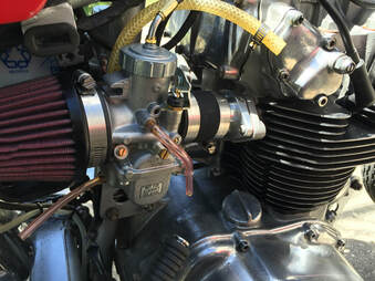
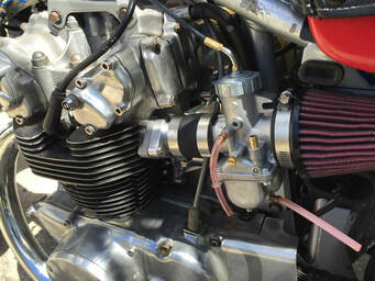
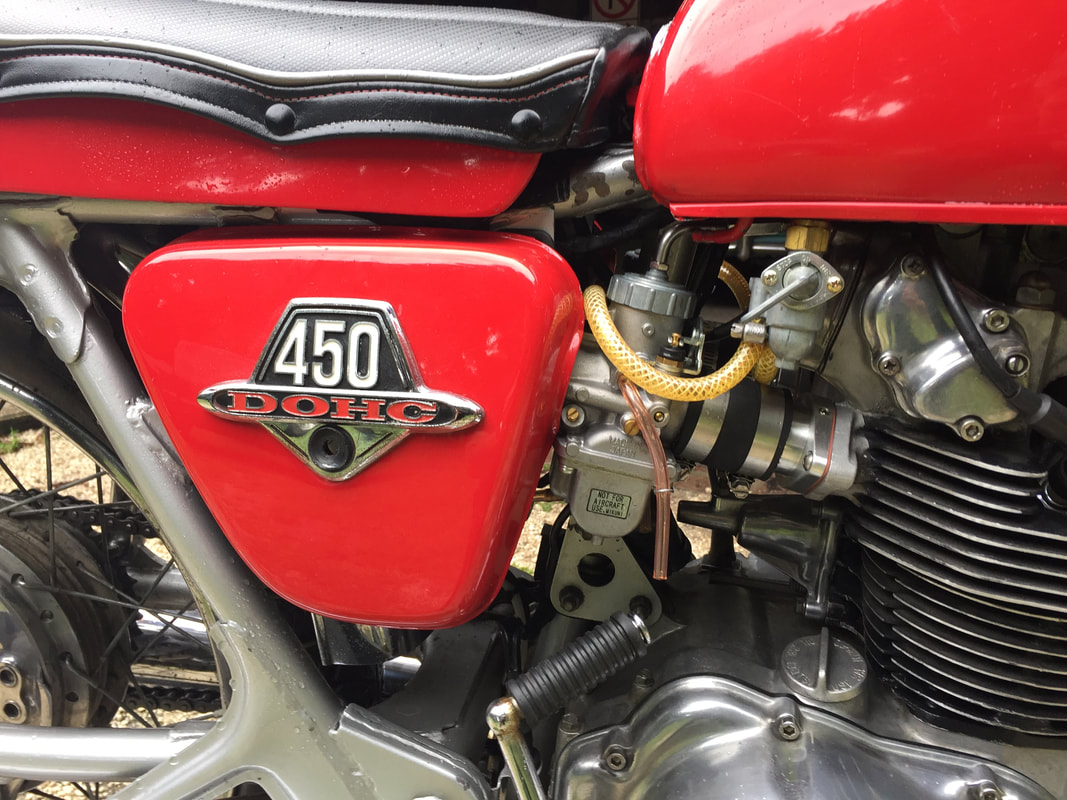
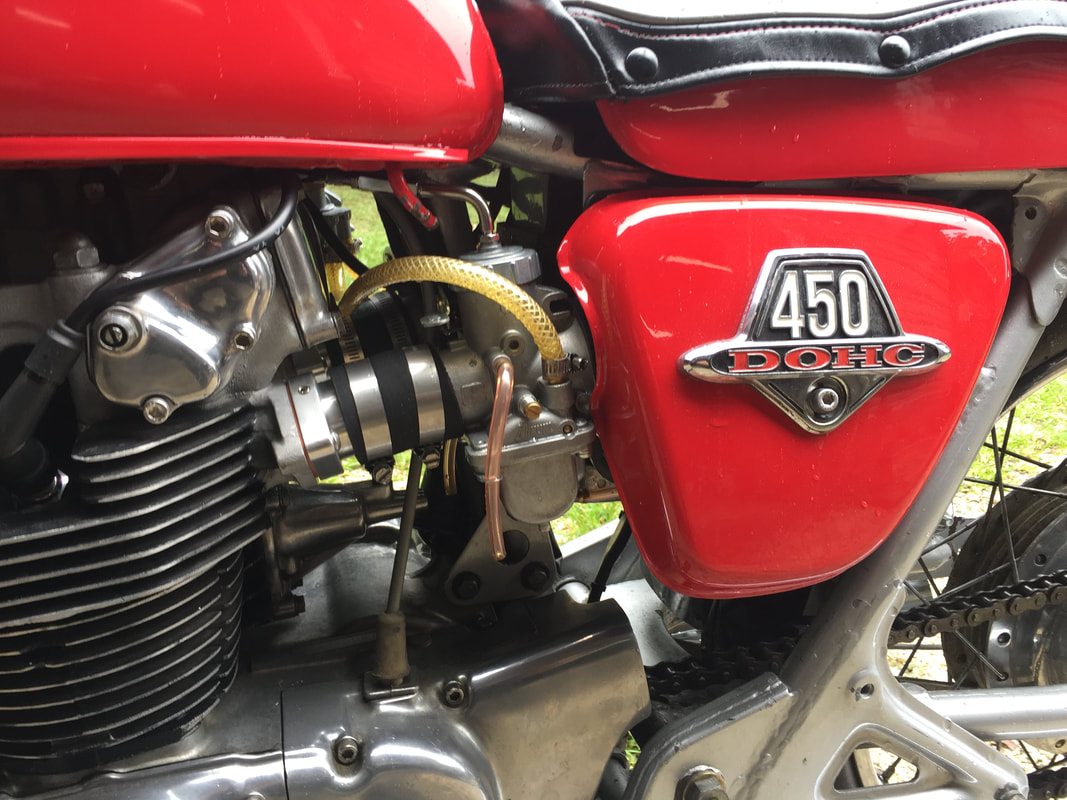
As seen in the pictures above, the bike looks great with or without side panels. The choice is up to you, but whatever you end up with, we're sure you'll find a lot to like about this carburetor conversion, like quicker start, better performance and years of trouble free riding. We hope the installation has been an enjoyable experience and we thank you for purchasing your Mikuni carb kit from Niche cycle.
As seen in the pictures above, the bike looks great with or without side panels. The choice is up to you, but whatever you end up with, we're sure you'll find a lot to like about this carburetor conversion, like quicker start, better performance and years of trouble free riding. We hope the installation has been an enjoyable experience and we thank you for purchasing your Mikuni carb kit from Niche cycle.
