A step-by-step tutorial on rebuilding a CB550K carb
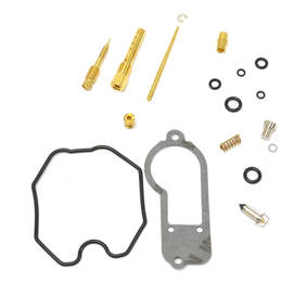 The CB550K rebuild kit available from Niche Cycle
About the CB550K
This kit fits both the 1977 and 1978 CB550K models. During the short production run of the CB550 model (1974-78), Honda may have used as many as three types of carburetors. So be absolutely sure you get the right kit for your make and model.
About the kits:
These kits are sold individually, so if you’re rebuilding all your carbs at once (which you should do), be sure to get a kit for each carb. Before we get started on the disassembly, I’d like to draw your attention to Niche’s carb kit. The kit, though not a Kehin brand, is very good quality. The parts are precision made and the gaskets look equal to, if not better than, the originals.
As we begin to put the carb back together, I’ll provide you with some close-up comparison photos. I don’t have the tools necessary to make microscopic, precision measurements, but in a visual comparison, the parts look like an identical replacement to the original part.
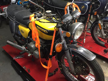 Project bike: 1977 CB550K
Technical complexity of this project
These instructions assume some basic mechanical ability and this project is not recommend for a mechanical novice or someone who gives up easily when challenged. That being said, this rebuild can be performed by almost anyone who can read and carefully follow instruction, has a modicum of mechanical skill and a few basic tools. Even if you don’t have the tools, they are easy to come by and cheap.
Our project bike
These carbs we’re using in this demonstration came from a fairly original 1977 CB550K. The bike sported a bad paint job, but other than that it was bone stock. You will notice in the photo the stock exhaust has been removed. We did this to test a new exhaust system for Niche Cycle.
The previous owner was planning to restore the bike. The carbs had been removed, carefully labeled and placed in a box. Much to my delight, that seemed to be the only wrenching done on this bike over the past 40 years.
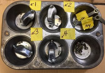 You can organize your parts in an old muffin tin
Getting prepared for the job
This project is going to take a minimum of several hours for some, a couple of days for others. So get prepared for the job before you start. Begin by finding yourself a clean work space. It’s possible you might have to start the project and finish up the next weekend, so organize your parts in such a way they won’t be lost.
It’s important to note that to do the job right, you really need to bite the bullet and completely disassemble the carb set. Otherwise you will not be able to remove the throttle slides or clean all the circuits and chambers. Even if you’re very experienced with rebuilding motorcycle carbs, disassembling a bank of carbs for the first time can be a bit daunting. The key to doing the job right is being organized and utilizing a methodical approach.
This guide does not instruct you on removing the carbs from the bike. It’s pretty straight forward and there are posts on you-tube and user groups that can help you with that. Just be sure not to damage or force anything when taking the old carbs off. I use the primary principal of medical ethics for my mechanical work: First, Do No Harm. If you break, damage, or lose parts during disassembly you will end up costing yourself time and money.
When doing a project like this, be sure you label the parts and take plenty of notes. I frequently buy off-brand Ziploc-type bags at Big Lots or discount stores. I get them in gallon and quart sizes. If you label parts (particularly hardware) and put them in a baggie, it makes life much easier when it comes to reassembly.
Over the years I’ve found common kitchen products are really handy when rebuilding carbs. A few years ago, I bought a couple of deep aluminum pots with lids for cleaning my parts at a yard sell for $2. I snagged some ice tongs for quarter. I use those for grabbing the parts out of the pots. And, I picked up some old muffin pans for keeping the parts sorted. I think they ran me about 50 cents apiece. Remember I mentioned being organized and methodical at the beginning of this exercise. The muffin pan is particularly helpful when working with multiple carbs. It keeps the parts separate but held together in one place.
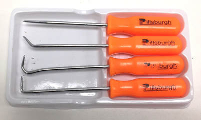 Tools like this inexpensive set are available at Harbor Freight and can be found online
Tools you’ll need
Make it easy on yourself. Use the right tool. If I’m very specific about a tool, it’s because using anything else will eventually cost you time and money. So if I say use an 8mm wrench and you don’t have one, then get one. If you use an adjustable wrench or a vice grip, you’ll ruin the nut or bolt and have to replace it. With tools so available and cheap on Amazon, eBay or from Harbor Freight, it’s just penny wise and pound foolish not to get the right tool.
One of the best tools you can use is a cell phone or digital tablet. I used to draw a lot of diagrams, but these days, I take lots of pictures when I take something apart. It helps me remember how to put things back together. I also use a little spiral-bound notebook and take lots of notes. These notes and pictures have saved me so much time and frustration on projects.
Here is a list of tools and items you will need:
- A #2 flat blade screwdriver
- A new #2, good quality Phillips head screwdriver
- A #3 Phillips head screwdriver
- 3mm Hex Key (Allen wrench)
- Small needle nose pliers (4-3/4”)
- Small needle nose Vice-Grip
- Small metal file (about 6” long)
- Small awl kit (available at Harbor Fright or on-line)
- ¼” drift (punch)
- Small plastic hammer
- 1 gallon of Pine-Sol
- Q-Tips (about 20 or so)
- 7mm, 8mm , 10mm combination wrenches
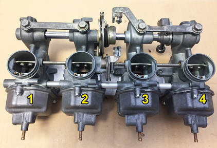 Kehin puts identifying numbers on the side of the mixing chamber
Identifying the carbs
The carbs are numbered by Kehin on the mixing chamber body, so you won’t need to do any labeling on these. Be sure you don’t mix up the parts from one carb to another. If at all possible, I always dissemble one carb at a time.
Looking at the choke side (the rear of the carbs), they are numbered 1-4 from left to right (see picture to right). This is important to know, because in these directions, I will be referring to the carbs by number and I don’t want anybody to confuse which is which.
 Pine-Sol is great for cleaning carbs
Getting the carbs clean
Let’s take a moment to talk a little about cleaning the carbs. Carbs on vintage bikes can run the gamut from pristine to useless, with most falling somewhere in between. Unless you’re the original owner, there’s no telling how many hands have been on them – both professional and amateur. While restoring bikes over the years, I’ve found mismatched jets and floats as well as missing gaskets, O-rings and springs, spider webs and even creatures burrowed inside old, dusty carbs. I’ve also found that some carbs are so corroded, they simply cannot be reused. But that’s pretty rare.
To begin this project, you’re going to want to give your carbs an initial cleaning. It will make them much easier to work with when you start the disassembly. There are as many preferences for cleaning as there are mechanics. I’ve been doing this for over 40 years and I recently changed my views about what I use to clean carbs. I used to soak carbs in a specialized agitating bath of toxic carb solvent. I also made the mistake of leaving them in too long. This can discolor carb bodies and erode the aluminum. Carb cleaner is bad for the environment, can ruin your parts, is horrible for your body (lungs, skin, eyes, hands) and causes cancer. Other than that, it’s fine to use. .
For that reason, I’ve moved to a more gentle approach. When doing an initial cleaning, I now use Dawn or mix of a 25-percent Pine-Sol 75-percent hot water – but not so hot as to deform plastic parts. These household cleaners cut grease and are much safer to use.
With the carbs off the bike, first remove all the gas from the carbs. The easiest way to do that is to remove drain screws in the float bowls. Don’t take the float bowls off at this time. This is just a cleaning so you can see what you’re doing. Put the carbs in a tray or plastic bin big enough to hold all four carbs. Use a stiff parts brush or scrub brush to clean up the carbs. I find an old tooth brush is helpful to get in tight spaces. You’ll be doing a more thorough cleaning of each individual carb once they are fully disassembled. Rinse the cabs and using compressed air, dry the carbs off thoroughly. After that, spray down the carbs (inside and out) with WD40. This will displace the moisture and keep uncoated metal parts from rusting. When the carbs are disassembled, I soak them in a 50-50 mix of Pine-Sol and hot water. I usually let them soak from 2 hours to 2 days depending on the condition of the carb.
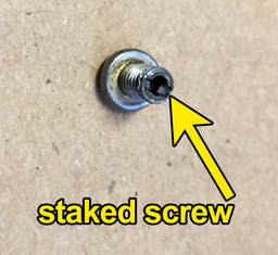 These screws are the little trouble makers
Carburetor Bank Disassembly
Step-1: Removing staked choke plate screws
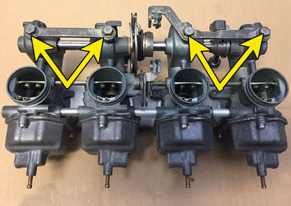
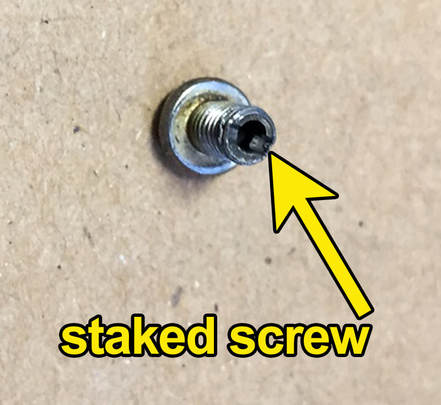
Once you’ve removed the manifold boots from the carbs, you’re going to want to tackle one of the more difficult tasks of the job. That’s removing the screws from the choke plates. Each of the valves on the choke is held in place by two very small (M3) Phillips-head screws. These screws have a hollow shaft and that allows the factory to “stake” or punch them once they are installed. This swells the ends of the screws to keep them backing out and being sucked into the engine. It works perfectly, but it also makes extracting the screws extremely difficult. I was looking for an easier way to do this and one buddy suggested using a Dremel Moto-Tool with a 1-1/4 metal cutting disc to shave down the back of the screw. You would have to be extremely careful and have a surgeon’s touch not to damage the carburetor. So I gave that a pass.
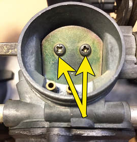 Keep track of these screws and don't lose them – you won’t find them in your local hardware store
I opted for a brand new, good quality #2 Phillips screw driver. While I have Snap-On tools, I bought a new Craftsman screwdriver for the job. The fresh tip fits perfectly and will resist striping. Besides the Craftsman driver was cheaper than a new replacement blade for my Snap-On screwdriver. Brand is not as important as fit. The driver needs to fit the screw head without any slop.
I’ve found on these particular screws, if the tip is worn on the screwdriver (it doesn’t take much), you’re going to strip the screw heads and suddenly realize you have much bigger issues. It’s easier to just to bite the bullet and get a new one. Under no circumstances should you use an impact driver. You will bend the rod choke rod, the choke plates or break the small plastic spacers used to keep the rod from moving around. If you do that, then you will then be challenged with the more difficult task of finding replacement parts. The trick is to put constant, steady pressure on the screw while turning it out. BUT, it’s a delicate balance to use enough strength to keep the tip from jumping out of the screw head, while not putting on so much pressure you bend the rod. Whew!
One the screws are out, you can relax. Disassembly is all downhill from this point on. You are going to want to label each choke plate and accompanying screws. Don’t mix them up. After filing down the flared tip of the screws, they can be reused; more on that in the assembly section.
Separating the carbs
To continue the disassembly, you’ll need to remove the brackets that hold the carb set together. There are two on the choke side and a large cast assembly on the manifold side. These should come off easily once the screws are removed. Be very careful how you handle the carbs once these brackets are off. You can bend the choke shaft and damage little bushes on the shaft.
To continue the disassembly, you’ll need to remove the brackets that hold the carb set together. There are two on the choke side and a large cast assembly on the manifold side. These should come off easily once the screws are removed. Be very careful how you handle the carbs once these brackets are off. You can bend the choke shaft and damage little bushes on the shaft.
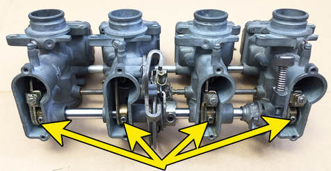 Remove these with a #2 Phillips-head screwdriver
Removing the throttle slide shaft and outboard carbs
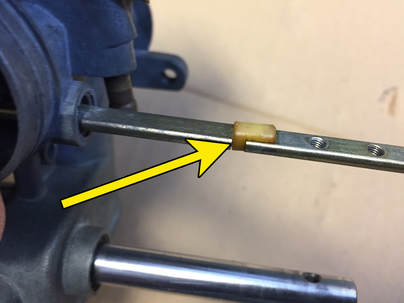
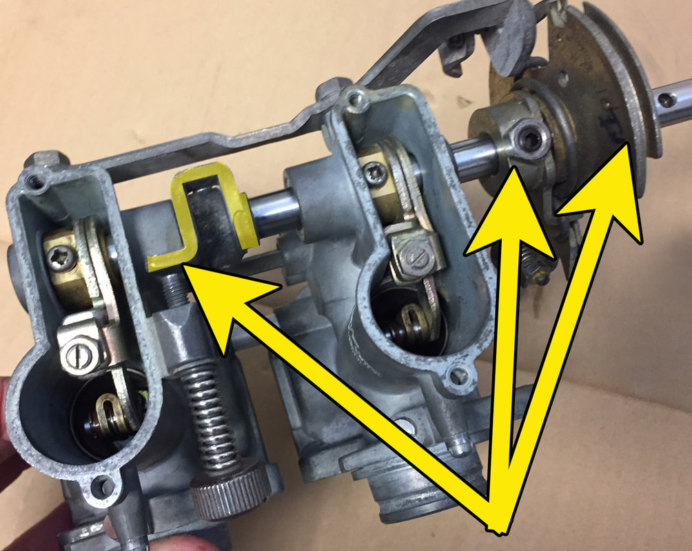
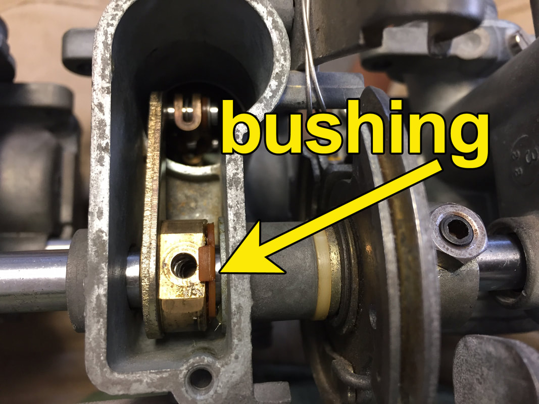
The next step is to loosen the screws that secure the throttle slide assembly to the throttle rod. This will allow you to remove the #1 and #4 carbs from the assembly. Start with the #1 carburetor. Remove the screw securing the slide assembly. There is a tiny split lock washer under the screw head. Be sure not to lose it. Place this screw in the bin with your other screws from the #1 carburetor. You can now gently slide the #1 carb from the assembly. Be sure you don’t mistakenly loosen the slotted screws attached to the throttle slides. These are for syncing the slides, you don’t need to remove them - so it’s best to just leave them alone for now. When the #1 carb is removed, you will notice that the throttle shaft and choke shaft remain, protruding from the #2 carburetor. The choke shaft has small plastic bushings which allow the shaft to move smoothly and keep it from binding within the carb bank.
Be extremely careful not to lose the little plastic bushings on the choke shaft. This is not included in the Niche rebuild kit and NOS parts are very difficult to find, so you want to take special care not to misplace them. These bushes should remain on the shaft after the carb is removed.
Be extremely careful not to lose the little plastic bushings on the choke shaft. This is not included in the Niche rebuild kit and NOS parts are very difficult to find, so you want to take special care not to misplace them. These bushes should remain on the shaft after the carb is removed. Keep in mind, it’s possible on carbs that have been previously disassembled or abused, the part might be missing or come apart in pieces. If it does, you’ll want to do your best to replace it with an NOS part or one from a salvaged set of carbs.
Removing the inboard carbs, 2 and 3
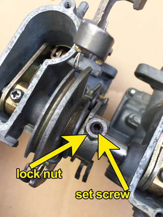
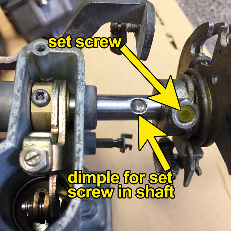
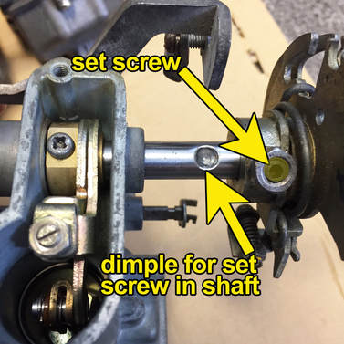
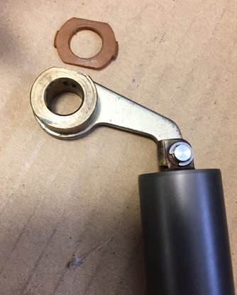
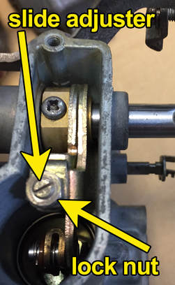
With the two outboard carbs successfully removed, you can now remove the throttle shaft and the one of the inboard carbs from the other. To do this, you’ll need to loosen the locknut on the throttle assembly bell crank (pictured to the left), then using a 3mm hex key (Allen wrench) to back off the set screw holding the bell crank in place. Once removed, you will notice that there is a dimple in the throttle shaft where this Allen screw resides (photo to the right). This keeps the assembly located in the proper position and makes reassembly much easier. Before you attempt to pull anything apart, take note of the small return spring on the choke rod. Note where it is attached and take a picture or make a simple drawing to help you remember. You can now carefully slide the throttle shaft out of the #2 and #3 carburetors. The shaft will exit from the side of the #3 carburetor.
With the two outboard carbs successfully removed, you can now remove the throttle shaft and the one of the inboard carbs from the other. To do this, you’ll need to loosen the locknut on the throttle assembly bell crank (pictured to the left), then using a 3mm hex key (Allen wrench) to back off the set screw holding the bell crank in place. Once removed, you will notice that there is a dimple in the throttle shaft where this Allen screw resides (photo to the right). This keeps the assembly located in the proper position and makes reassembly much easier. Before you attempt to pull anything apart, take note of the small return spring on the choke rod. Note where it is attached and take a picture or make a simple drawing to help you remember. You can now carefully slide the throttle shaft out of the #2 and #3 carburetors. The shaft will exit from the side of the #3 carburetor.
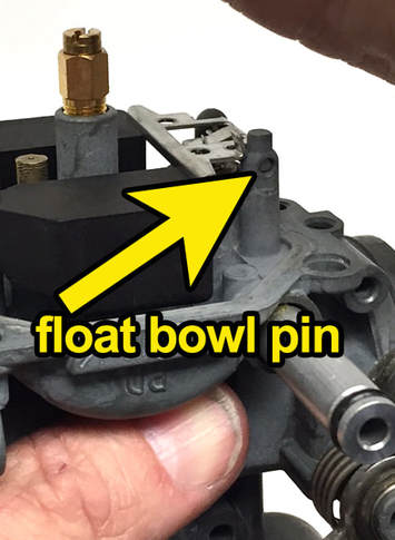 Be very careful removing this pin if it is stuck
Carburetor Disassembly
With the carbs removed from the shafts, you can now get to the work of disassembling and cleaning the individual carburetors. I highly suggest you clean each carb individually. That way if you get mixed up on where a part is located, you can refer to one of the other carbs.
Let’s start with carb #1. This process will be repeated with the other three carburetors. With the throttle rod removed, the throttle slide will pull out. Be sure to set the slide on a soft cloth. You do not want to scratch it. Remove the three Phillips-head screws securing the float bowl. There is a small pin that holds the float in place. Using a tiny pick, drift or nail (smaller than the hole), gently tap the pin until it protrudes from the opposite side of the other float tower. I found the pick in the Harbor Freight small pick set is perfect for doing this. It only costs about $2. That set is pictured in Fig. 3. If the pin doesn’t want to move with some gentle tapping, spray on a little PB Blaster, Kroil, Mouse Milk or CRC Knock’er Loose on the pin. Give the penetrating oil an hour or so to do its work. If you get too aggressive and tap too hard or push too hard on the pin, you’ll break off the float bowl tower. At that point, the carb is ruined. That would be a very expensive mistake – one you want to avoid. So be patient.
If it doesn’t want to come loose, spray it again generously, and after a couple of hours, tap it again. Repeat until it comes out. I’ve never had one not come out – even when horribly corroded. Once it protrudes from the other side, the pin can be pulled out with a pair of small, needle nose pliers. Be sure you clean it up with a Scotch-Brite pad before reinstalling.
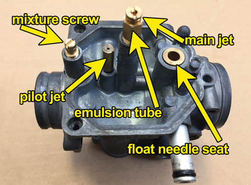 The removable, internal parts of the carb
With the pin removed, the float and needle valve should easily lift out with the float. Take care not to lose the needle valve as you remove it. Use extreme care when handling the float. It is very delicate and can be easily damaged. If your carbs have worked well in the past, the float tabs are probably still in proper adjustment. So be careful not to bend the float tab. You can test your float by placing it in a bowl of water. If after an hour or so, both sides are floating evenly, you’re in good shape. If one side has dropped, or if you can hear fluid swishing around inside the float, or if you find the float sitting on the bottom of the bowl, then you’ll need to replace it.
As gasoline ages, it changes from a liquid into a sludgy, horrible smelling, varnish-like material that plugs up carbs something awful. The longer gas sits in your carb the worse it gets. After a couple of years this stuff can harden to the point where it will block nearly every circuit and jet in the carb. If your carbs are really corroded or varnished up, removing any part can be difficult. I’ve had jets snap off as I attempt to take them out. In this case, you might do well to soak the carb in the 50/5O mix of water and Pine-Sol. You'll want to leave it the carb soaking overnight or longer if it’s bad. I’ve found, if the water is hot, it will work better. After soaking, you’ll be able to disassemble the carb easier. See more about the cleaning process below.
As gasoline ages, it changes from a liquid into a sludgy, horrible smelling, varnish-like material that plugs up carbs something awful. The longer gas sits in your carb the worse it gets. After a couple of years this stuff can harden to the point where it will block nearly every circuit and jet in the carb. If your carbs are really corroded or varnished up, removing any part can be difficult. I’ve had jets snap off as I attempt to take them out. In this case, you might do well to soak the carb in the 50/5O mix of water and Pine-Sol. You'll want to leave it the carb soaking overnight or longer if it’s bad. I’ve found, if the water is hot, it will work better. After soaking, you’ll be able to disassemble the carb easier. See more about the cleaning process below.
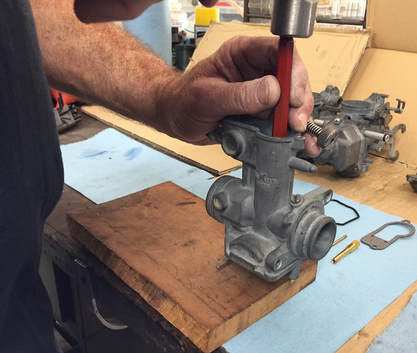 Very gently tap out the throttle slide needle guide
Back to the carb disassembly, you can now use a flat blade screw driver to remove the main jet and the mixture screw. Be sure you don’t lose the spring under the mixture screw. Under the spring there is a tiny washer and O-ring. The Niche kit has a replacement for both, but you’ll need to remove the old one from the hole. The tools in that tiny pic kit may prove helpful if these parts don’t drop out. Sometimes they don’t. Be sure you don’t leave them in there. You’ll get an air leak from the old, cracked O-ring. Use a small flashlight and magnifying class or loop to see in the chamber if you have too.
When removing jets with a screwdriver, always make sure the blade of your screw driver fits the screw properly or you risk breaking the head off the jet. Brass is really soft. To remove the emulsion tube you‘ll need a 7mm wrench.
The pilot jet is pressed in. You’ll need a very small pair of needle nose vice grips to pull this jet out. Grasp the jet with the vice grips, then move it side to side as you pull it straight out. Be careful not to wallow out the hole for the jet. On eBay I found 4-3/4” locking nose pliers for under $6. These would be perfect for this. You can find similar pliers at Lowes, Home-Depot, Ace Hardware or Harbor Freight.
You can normally use your fingers to pull out the aluminum fuel tube. It’s only being held in by an O-ring. Sometimes old O-rings get dried up and hard, and it makes it a little more difficult to get them out. Just be careful if you use a tool not to crush the end of the tube. These are very thin.
With all the internal parts removed, you now only need to tap out the throttle slide needle guide. Note: unless you are replacing it, you really don’t need to remove this part. If you choose to remove it, use a small drift and set the carb on a block of wood (see photo to left). Gently tap the throttle slide needle guide out of the bottom of the carb body through the float area. I use a 1/4” Craftsman drift to push out the guide. It just happens to be a perfect fit. When removing parts, I try not to damage anything if possible.
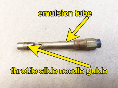 The guide sits under the emulsion tube
Just a note, once they’re cleaned, the jets, emulsion tube and guide can be cleaned and reused if necessary.
The one part of the carb you don’t want to attempt to remove is the fuel needle seat. I doubt replacement parts are available and you’d probably destroy it getting it out. So, after a good cleaning, this part can be polished to eliminate any old varnish residue that might be left behind. I’ll have more on that later.
The one part of the carb you don’t want to attempt to remove is the fuel needle seat. I doubt replacement parts are available and you’d probably destroy it getting it out. So, after a good cleaning, this part can be polished to eliminate any old varnish residue that might be left behind. I’ll have more on that later.

Cleaning Tips
I mentioned before about cleaning one carb at a time. In this case, all the carburetors are basically the same. So you could disassemble and clean two carbs while leaving two carbs intact. That way, if you get into trouble putting the carb back together, you always have a complete carb to look at for reference.
With all the internal parts removed. You can now thoroughly clean the carburetor. As I mentioned before, I suggested a 50-50 mix of Pine-Sol and water. I recommend using Pine-Sol and not any other cheap, copy-cat product. Whatever is in Pine-Sol, it works. The chemical composition is such that you can clean out the old gas products and dirt, without damaging the metal on the carb (unless you leave it for more than a couple of days). It’s also a lot cheaper and safer than the carb cleaner you buy at an auto parts store. Of course, if you leave it soaking for more than 48 hours, or use a stronger solution, you might see some damage to the metal. With this solution, I’d start checking the parts after 24 hours, just to make sure the aluminum isn’t going dark. If you left an O-ring in, it might put a black sooty coating the nearest piece of aluminum. You’ll have to clean this off. WD40 works well for that. Use tongs or gloves to pull the parts from the solution. This strength of Pine-Sol can leave your hands very dry and itchy.
I find that keeping the solution hot helps it clean better. I don’t know if heated Pine-sol at this solution is toxic, so I’d do this in a well-ventilated area and not in the kitchen or next to your kid’s high chair. By the way, never use Simple Green for cleaning aluminum. It can start breaking down the metal after 15 minutes of exposure.
If you can, use this Pine-Sol formula in an ultrasonic cleaner, or if you created some kind of agitating parts mixer, that’s even better. After several of hours soaking in this bath you’ll be able to remove all but the worst of any old gas residue. Sometimes you need use a wire brush to get the varnish out of the bowl. You might also need to use a strand of copper wire to clean the circuits. If you’re a guitar player (like me) or you have a friend who is, I’ve found that an old 010-.014 high E guitar sting works great for this. I keep several sizes of guitar strings on a loop.
Once you’re done soaking, be sure you thoroughly rinse the parts with clean water (high pressure when possible) and then dry with compressed air. I’d also recommend spraying the parts with a coat of WD-40. WD-40 is designed to displace moisture, so it will help keep parts from corroding.
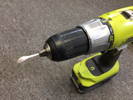 A drill with a Q-Tip in the end is great for polishing the needle seat .
The polished seat looks good as new
There is one more step to cleaning that I do before assembling the carburetor. I take a few minutes to polish the seat for the needle. This is not an easily replaceable part on these carbs and as far as I know, it doesn’t come in any kits. But a good polishing is usually all the seat needs to work like new. I like to use an electric drill with a half a Q-tip in the end. Place a very small dab of Semichrome polish on the Q-tip. Then insert the Q-tip into the seat and spin the drill for about 30 seconds using light pressure. I then use the other side of the Q-tip to clean up and polish the seat. I usually use at least one more Q-tip to make sure it is perfectly clean, but go ahead and feel free to use as many as you like – they’re cheap! When the seat is gleaming (nothing polishes as well as Semichrome) I spray a little brake cleaner through the orifice just to make sure no polish is left behind. As a final step, I blow compressed air though the hole.
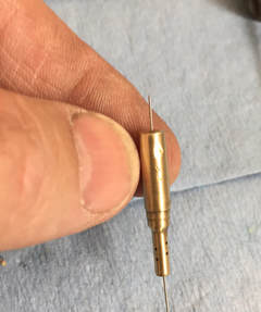 An old guitar string works great for cleaning jets
Assembly
With all the carburetors thoroughly cleaned, it’s time to start the reassembly process. There are a number of ways to reassemble the carbs, but I began with the pilot jet (also known as the low-speed jet). A new pilot jet is not included with the kit, so this jet will need to be cleaned and checked before it can be replaced. Again, the high E guitar string works great for this. But you can also use a jet or welding tip cleaning tool set (looks like a set of different size wires in a case) or a very stiff piece of wire to run though the jet to ensure it is clear. Be careful you don’t do anything to increase the jet size. On my carbs, the pilot jets were solidly blocked and it took several attempts to clean them. If air does not pass though this jet, the bike will not idle properly. If you cannot see light though the jet, or blow air though it, keep cleaning until you can. Be sure all the holes are clear. I used a jet cleaner, guitar string and re-soaking to finally clear the hole. Once the pilot jet is clear and clean, you can push it back into place. Give it a very gentle tap with a tiny plastic hammer or the end of a screw driver to ensure it is seated. It might also be a good idea to put a tiny amount of Blue Loctite where the jet seats to hold it in.
With all the carburetors thoroughly cleaned, it’s time to start the reassembly process. There are a number of ways to reassemble the carbs, but I began with the pilot jet (also known as the low-speed jet). A new pilot jet is not included with the kit, so this jet will need to be cleaned and checked before it can be replaced. Again, the high E guitar string works great for this. But you can also use a jet or welding tip cleaning tool set (looks like a set of different size wires in a case) or a very stiff piece of wire to run though the jet to ensure it is clear. Be careful you don’t do anything to increase the jet size. On my carbs, the pilot jets were solidly blocked and it took several attempts to clean them. If air does not pass though this jet, the bike will not idle properly. If you cannot see light though the jet, or blow air though it, keep cleaning until you can. Be sure all the holes are clear. I used a jet cleaner, guitar string and re-soaking to finally clear the hole. Once the pilot jet is clear and clean, you can push it back into place. Give it a very gentle tap with a tiny plastic hammer or the end of a screw driver to ensure it is seated. It might also be a good idea to put a tiny amount of Blue Loctite where the jet seats to hold it in.
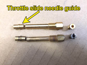
Next we can move onto the replacing the throttle slide needle guide. You can see a nice comparison of the old and new in the photo on the below. Except for condition, both old and new look identical. If you look at the guide carefully, you will notice one end has a thin wall, the other is thicker and beveled. When replacing the tube, place the thin-walled side first into the top of the emulsion tube chamber. This is the side that should stick out into the mixing chamber. Again, using the Craftsman ¼” drift, gently set guide into place. Do not tap hard. Once in place, gently tap it with a plastic hammer or end of a screw driver and it will pop right into place. If it doesn’t, check to make sure the guide isn’t in upside down.
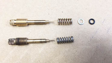 Don't forget the spring, washer and O-ring in that order
Next you can screw in the emulsion tube. Use a 7mm wrench to tighten the tube. After that, replace the main jet and tighten with a flat blade screw driver. Don’t be alarmed if you see a few threads sticking up from the emulsion tube. It’s supposed to be that way.
Don't forget the spring, washer and O-ring in that order
Next, we’re on to the mixture screw also known as the pilot screw. First look down the shaft (chamber) where mixture screw resides and make sure there are not remnants of the old gasket or washer left behind.
Don't forget the spring, washer and O-ring in that order
Next, we’re on to the mixture screw also known as the pilot screw. First look down the shaft (chamber) where mixture screw resides and make sure there are not remnants of the old gasket or washer left behind.
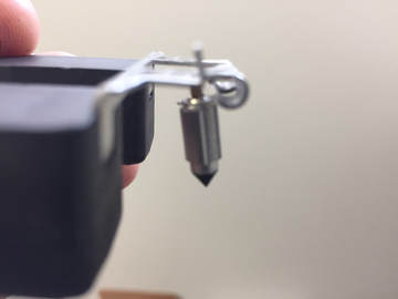 The float needle hangs on a tang extending from the float
ou should also be able to blow air through into the hole for the mixture screw and have it exit into the mixing chamber of the carb. If not, go back to soaking and using high pressure air to clean out the hole. Rarely, people have broken off the tip of the needle by screwing it in too hard. If that is the case, you will need to force it out with air pressure. If you look down the throttle slide shaft, you will see a very tiny hole directly behind the hole where the needle resides (towards the manifold side of the carb). That is the hole where the mixture screw circuit exits. Try adapting a small hose to your compressed air nozzle or use a can of compressed air with the straw attached to blow out that hole. Once the hole is clear (if blocked) you can assemble the mixture screw. Examine the screw in the photo above. Make sure the needle tip of the screw is intact and not bent. If bent, the screw must be replaced. With the screw held upright, slide the spring over the tip of the screw. Follow the spring with the small flat washer. Spray a dab of WD-40 or place a very slight layer of grease on the O-ring. Slide the O-ring on after the washer. Now, with the carburetor sitting upright, screw in the air screw. Using a small screwdriver, gently screw it in until just snug. DO NOT OVER TIGHTEN! Now, back off the screw, 1-1/4 turns.
The next step is to replace the float and float needle. Spray a little WD-40 onto the end of the float pivot pin and into the holes on each end of the float towers where the pin will be placed. Be extremely careful when handling the float. You do not want to bend the float tab or damage the float. Holding the float with the notched side of the float facing down, slide the float needle’s wire hoop onto the tang on the float. Now, with the carburetor upside down, carefully place the float in between the float towers and slide the pivot pin through the holes in the towers, securing the float. You might need to very lightly tap the pin into place, so both sides are flush or inside the edges of the towers. DO NOT FORCE THE PIN IN. It should not take more than a light tap for the pin to fit into place.
The next step is to replace the float and float needle. Spray a little WD-40 onto the end of the float pivot pin and into the holes on each end of the float towers where the pin will be placed. Be extremely careful when handling the float. You do not want to bend the float tab or damage the float. Holding the float with the notched side of the float facing down, slide the float needle’s wire hoop onto the tang on the float. Now, with the carburetor upside down, carefully place the float in between the float towers and slide the pivot pin through the holes in the towers, securing the float. You might need to very lightly tap the pin into place, so both sides are flush or inside the edges of the towers. DO NOT FORCE THE PIN IN. It should not take more than a light tap for the pin to fit into place.
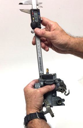
It’s always a good idea to check the float levels. I was pretty sure nobody had been in these carbs since new, but when I checked the float levels they were way off. Only one carb was at the correct setting. So it’s always a good idea to check.
Rather than use a metric ruler, I prefer using the depth gauge on the end of a digital caliper. These are so cheap these days you can get a decent one on-line or at Harbor Freight for under $15. This is an essential tool and no mechanic should be without one.
Holding the carb upside-down, give the floats a couple of light taps to settle them in place and then measure from the top edge of the float to the surface of the carburetor body where the float bowl is attached. The correct distance from the top of the float to the surface where the float bowl is mated is 14.5 mm.
By carefully bending the tab with a small pair of needle nose pliers, you will be able to adjust the float bowl height. Keep in mind that it will be extremely difficult to adjust within a half a millimeter.
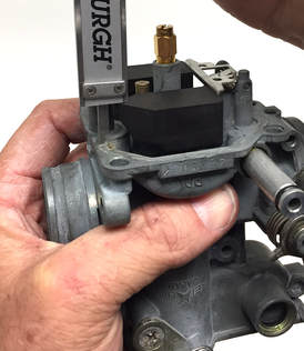
So, if you are at 14mm or 15mm, you are close enough. My carbs were working and ranged from 12mm to 18mm. These were more than likely, right from the factory. Additionally, repeated attempts to bend the tab to achieve a perfect 14.5 mm are eventually going to fatigue the brass until tab breaks. Then you’ll need a replacement for the float.
Now, with all parts in place you can put on the float bowl cover. The O-ring around the base of the carburetor float bowl should be held in place with the little half-moon-shaped nibs that protrude into the channel for the O-ring. They do an okay job of holding the O-ring in place, but I find it easiest to place the gasket on the float bow sitting upright. Then, holding the carb upright fit the float bowl onto the base of the carburetor. I always watch to make sure the gasket stays in place until the bowl is completely seated. Once on, keep the bowl in place with your hand while you screw in the float bowl screws. Any time you find a component with multiple screws, it usually is best to snug screws first, then go back and fully tighten them. Such is the case with the float bowl. This allows the O-ring to seat properly against both surfaces without being squeezed out and getting ruined.
Now, with all parts in place you can put on the float bowl cover. The O-ring around the base of the carburetor float bowl should be held in place with the little half-moon-shaped nibs that protrude into the channel for the O-ring. They do an okay job of holding the O-ring in place, but I find it easiest to place the gasket on the float bow sitting upright. Then, holding the carb upright fit the float bowl onto the base of the carburetor. I always watch to make sure the gasket stays in place until the bowl is completely seated. Once on, keep the bowl in place with your hand while you screw in the float bowl screws. Any time you find a component with multiple screws, it usually is best to snug screws first, then go back and fully tighten them. Such is the case with the float bowl. This allows the O-ring to seat properly against both surfaces without being squeezed out and getting ruined.
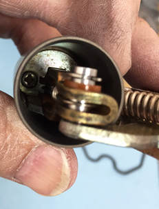
Next, you’re going to want change the needle in the throttle slide (if you decide to replace it). There are two very small (probably M3) screws in the bottom of the throttle slide. You can use a #1 Phillips screw driver to remove these screws. Be extremely careful not to damage the needle or scratch the slide when doing this. Coming from the factory, the needle clip is supposed to reside in the #3 position. But my clips were in the #2 groove, so I’m putting them back the way they were. A couple notes about the slides. The number 2 slide should have a plastic shim where the throttle slide goes though. Be really careful not to break it. If the tabs are damaged, you can hold it in place with a little dab of grease.
The number 2 slide is also the only non-adjustable slide. Be careful not to lose the spring on the arm when stretching the arm to remove or replace the spring. The slide can be put on backward and this would really mess with your performance.
The number 2 slide is also the only non-adjustable slide. Be careful not to lose the spring on the arm when stretching the arm to remove or replace the spring. The slide can be put on backward and this would really mess with your performance.
Look on the bottom of the slide. One side is flat the other has a slight upward curve. Be sure the curve faces the front or choke side of the carburetor. The arm on the slide should fall toward the curve. Here’s a tip that will make it easier to get the screw in place. Set the screw on your screw driver. Warp a short piece of tape around both holding the screw to the tip. Once in, use a small pair of needle nose to remove the tape. I believe these are stainless screws, and that’s why a magnetic screw driver won’t work.
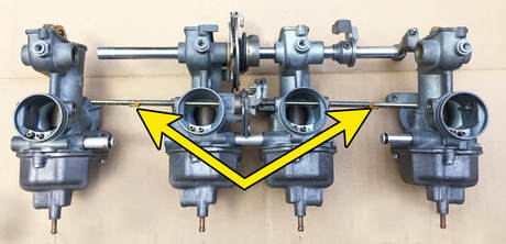
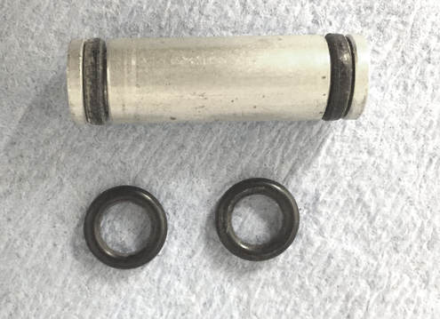
Before assembling the carb bank, we have another task that needs to be completed. You will need to put new O-rings on the fuel rail tubes. You have to be sure these tubes go back into the correct place on the carburetors. There are two short tubes and one long one. The short tubes go between carbs 1 and 2, as well as carbs 3 and 4. The long tube is in the middle and goes between carbs 2 and 3.
I like to use a dental pick to remove old O-rings, or you can just cut them out. Be careful not to damage the surface of the tube when doing this. Any nicks or burrs can damage an O-ring and cause fuel to leak. To slide the new O-rings onto the tube, spray the O-ring with a little WD-40 or use place a thin layer of grease over the O-rings. You will also need a little lube on the O-rings when you insert them into the carbs.
Assembling the Carb Bank
Most of the hard stuff is done and at this point it’s kind of fun to watch it all come together. There are still a couple of minor challenges ahead, but nothing you can’t handle.
Start by laying out your rebuilt carbs in the correct 1-4 position. Now let’s examine the fuel rail tubes and look at where they belong (see 4 paragraphs above). When in place, these tubes should be snug, but you should be able to rotate them with your fingers. If they’re sloppy, they will leak fuel.
We will first assemble the bank in pairs - carbs 1 and 2, then 3 and 4. After that, we will join the two pairs.
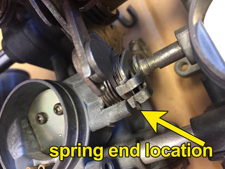
Begin by placing a few drops of WD40 on the fuel rail tube and insert fuel rail tube and choke shaft into their proper places between carb 1 and 2. Now, insert the choke rod with the lightweight spring through carbs 1 and 2. Pictured to the left is the end of the choke rod, which is different than the one for carbs 3 and 4, as well as the little spring. You should note where the spring is placed. Hopefully you’ve kept the spring in place on the rod. The spring fits in only one direction, so if it doesn’t work, you’ll have to pull it out and turn it over. Taking care not to damage the small plastic bushing on the rod, insert the choke rod through the right side of carb 2 into carb one. You won’t be able to do it any other way, because the passage on carb 1 is sealed.
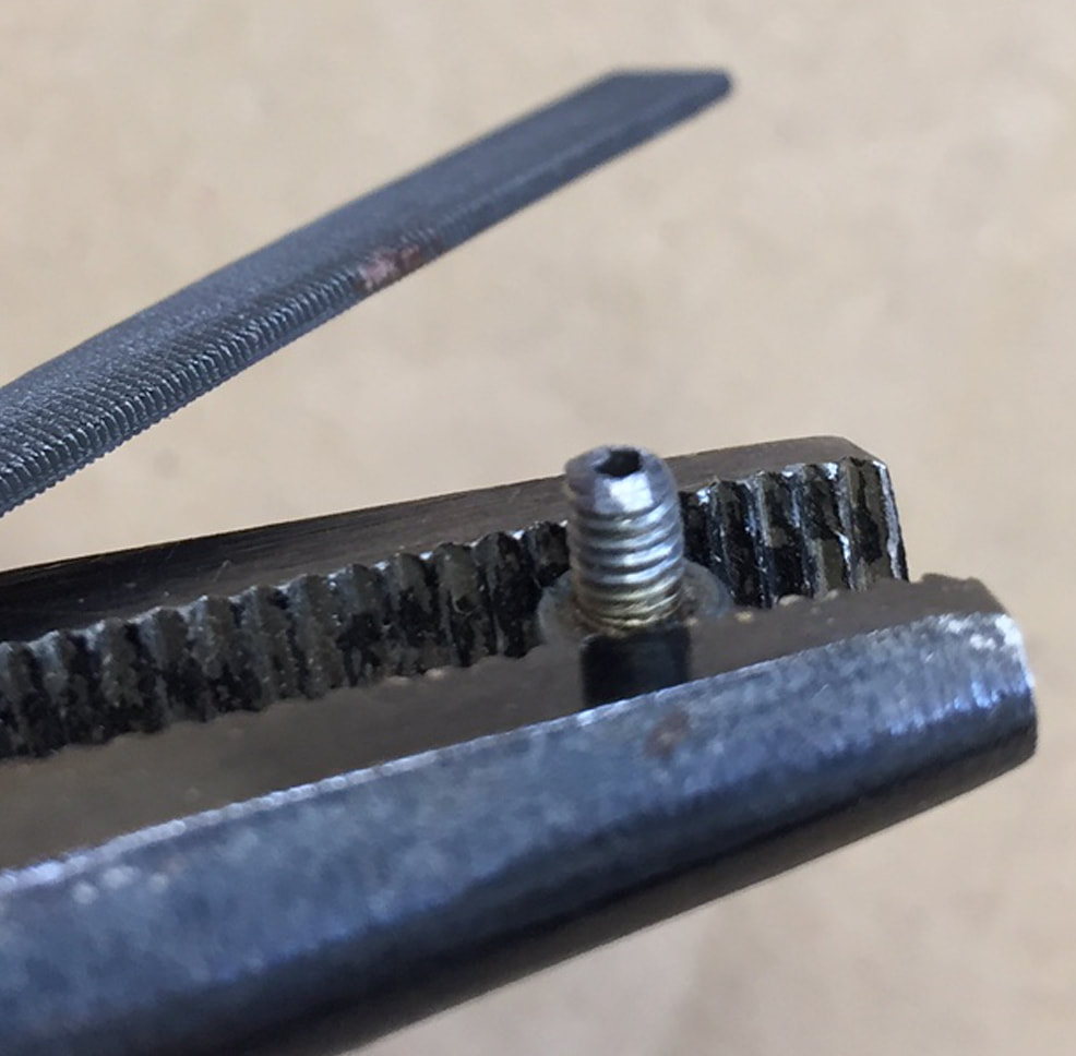
With the fuel rail tube and choke shaft in place, you can attach the choke plates. You can identify the outside of the plate because there is a dimple on the outside of each plate. Make sure this dimple is facing you when you assemble the choke plates to the choke shaft. This is important: YOU WILL NEED TO FILE THE CHOKE PLATE SCREWS BEFORE YOU SCREW THEM INTO THE CHOKE SHAFT! You might remember I mentioned these screws were staked to keep them from falling out and being sucked down the carburetor. That same process also makes them hard to get out and nearly impossible to put back in unless they are filed down. It’s not a big deal, it just takes a little time. To do this, I used a pair of needle nose vice grips and a small file. I first removed the area of staking (where the head is spread out), this probably accounted for about two or three threads. Then I rounded over the bottom threads of each screw. It probably took about 5 minutes for each screw. Here are a couple of important tips. Use the right size tools. If you don’t have small vice grips and a small file, get them at Harbor Freight, Home Depot, Lowes or online. If you try to use big stuff, you’ll run into problems. Also, do this on top of a clean work space, or an old sheet or something. Don’t do this while sitting on shag carpet. I promise, you will lose a screw. Chances are the first couple times you try to clamp the screw in the vice grips, it’s going to pop out and go sailing. You want to be able to find it unless you can see it – hence the sheet. Keep in mind this is a really small screw and hard to work with. But once you’ve done one, the rest are a breeze.
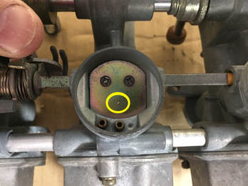 The dimple is shown inside the yellow circle. This dimple must always face you
As you are trying to fit the choke plates in place, you will notice that the choke plate flips from the bottom up. Lay the plate in place on the carb and see if it will work before you put the screws in. You need to rotate the choke arm which is now under pressure from the larger spring on carb 2. Rotate the choke arm upward. You might want to hold it back with a rubber band or tie wrap. When you do this, it will become obvious where the choke plate was because of discoloring of the choke rod. Remember the dimple on the plate goes to the outside. Once you figure out how the choke plate fits, put the two screws though the plate and into the rod. Snug them up, but do not tighten them. Once everything is in place and working properly, go back and put BLUE Loctite on the screws. Be sure you don’t do that now. If you have to disassemble for some reason, having the Loctite on the screws could cause you a lot of work later. Wait until the carbs are completely finished and bench tested for leaks before you put on Loctite. Do not use red Loctite. Parts must be heated to be removed and this could damage the carbs.
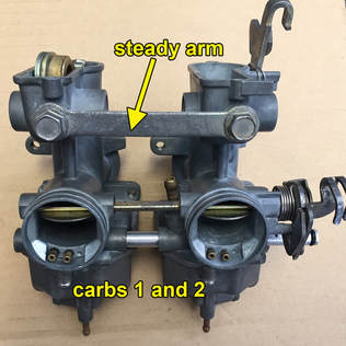
With the fuel rail, choke arm and plates in place on carbs 1 and 2, you can put the steady arm in place between the carbs. Use a 10mm wrench to tighten the hex head bolts. This will keep the carbs from moving around and damaging the choke rod. Moving onto carb 3, you will need to replace the throttle shaft. You can begin by placing the throttle slide assembly into the mixing chamber of the carburetor. Insert the throttle shaft though right side of carb 3, carefully passing it through the slide assembly for that carb. Rotate the idle stop (which is fixed in place with a pin and should not be removed) to the top. Thread the 5mm Phillps screw though the top of the slide assembly and into the shaft. Slide the bell crank over the throttle shaft on the left side of carb 3.
The set screw will face carb 3. Find the dimple in the shaft where the set screw should be placed (see photo). If you’ve got the shaft on correctly, the dimple should be facing upward. The set screw should be approximately on line with the idle stop on the throttle shaft. Now, lightly screw Allen-head screw into the dimple until you feel it grab. Rotate the bell crank to make sure it is not slipping, then sung up the set screw. Use a 10mm wrench to tighten the lock nut securing the set screw to the throttle shaft. Once you’ve completed the final assembly (at the end of instructions) and you’re sure everything is right, you can go back and place a drop of BLUE Loctite on the set screw. DO NOT USE RED LOCTITE!!! Red Loctite must be removed with heat which can damage the carburetor.
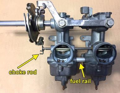
Put a few drops of oil, WD40 or silicone spray onto the O-rings on the fuel rail that goes between carbs 3 and 4. Remember, that’s a short fuel rail too. Now, while carefully sliding the throttle shaft through the throttle slide assembly for carb 4, join the fuel rail and carbs 3 and 4 together. Thread the 5mm Phillps screw though the top of the slide assembly for carb 4 and into the shaft. Securely tighten the screws for carbs 3 and 4 that secure the throttle slides to the throttle shaft. Do not touch the throttle adjustment screws. Now, you’ll want to put the choke control rod in place. The choke control rod for this side looks a bit like a two-pronged fork, bent at 90-degrees. Place the choke rod though the left side of carb 3 and into carb 4. Put the choke plates in place and sung the screws, but do not tighten. You'll tighten everything up as part of the final assembly, after everything is lined up. Now, put the steady arm in place and secure it with two hex-head bolts and a 10mm wrench. When you’ve completed that step, it should look like the photo to the right.
Okay, we’re almost there, but we still have a few small challenges ahead. First, you'll have to join the carburetor pairs together. If you haven’t done it already, lubricate and place the O-rings on the long fuel rail. Make sure the O-rings are lubricated before you attempt to insert them into the carburetor body. If you don't, the O-rings will be damaged and your carbs will leak fuel. The long fuel rail sits between carbs 2 and 3. Insert the fuel rail into the right side of carburetor 2. Now carefully slide the throttle shaft extending from carb 3 and 4 into the opening and through the slide assembly for carb 2.
Okay, we’re almost there, but we still have a few small challenges ahead. First, you'll have to join the carburetor pairs together. If you haven’t done it already, lubricate and place the O-rings on the long fuel rail. Make sure the O-rings are lubricated before you attempt to insert them into the carburetor body. If you don't, the O-rings will be damaged and your carbs will leak fuel. The long fuel rail sits between carbs 2 and 3. Insert the fuel rail into the right side of carburetor 2. Now carefully slide the throttle shaft extending from carb 3 and 4 into the opening and through the slide assembly for carb 2.
Note, carb 2 has a plastic bushing that rests on the right side of the assembly. Be very careful when handling this bushing, I don’t believe there are replacements available. There are little tangs that hold the bushing in place on the arm of the slide assembly. Should one or both the tangs break, use a little grease to hold the bush in place.
Don’t put the screws into the throttle slide arm yet. You might have to pull the carbs apart to get the choke lever rods seated correctly and working.
Don’t put the screws into the throttle slide arm yet. You might have to pull the carbs apart to get the choke lever rods seated correctly and working.
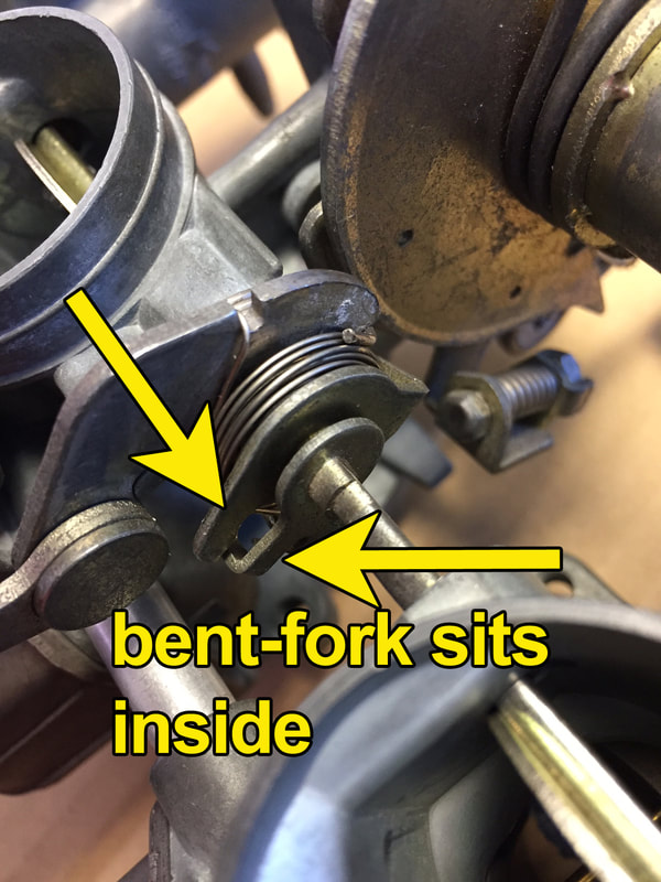
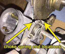
You can see that the bent forked end on the carbs 3-4 nests inside the choke shaft end from carbs 1-2. The 1-2 is the choke shaft with the spring on it. Even though I take pictures of this, every time I put one back together, I have to study and play with it a bit. When everything is in place the spring fits nicely in the slots (see picture below left).
Get a paper clip, straighten it out, and then put a new tight bend (hook) in the end. This little homemade tool works great for manipulating the spring where there’s not enough room for fingers. When the plates are in place, use your clip tool to grasp the spring so you can drop it in the space cut for it in the forked end of the choke rod (see picture to right).
This is perhaps the most difficult part of the job. But rest assured, if you made it this far, you, will be able to get that spring in place. The bottom line is, when you pull up on the choke lever, all four choke plates must move harmoniously. When the lever is released, all the plates must move together to a horizontal position. If your plates are doing this, then you have done the job correctly. If half the plates do this, then you got some work to do. I found I was able to use my spring without winding it around twice to tighten it. But if your spring is worn, you might have to loop it around once to have enough tension to draw the plate up.
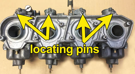
Now, carefully fit the two carb bank halves (1-2 and 3-4) together. Do not force the fit! If it does not move in easily, find out where the interference issue is, fix it and then proceed carefully. Hopefully, you took note of where the choke lever spring was before disassembly and maybe even took some pictures as this part is a bit hard to describe. As the halves come together, you will see the choke rod from 1 and 2 fits together with the choke rod from 3 and 4. This positioning is best demonstrated in the photo above.
Once you have the choke rod in place and working, you can insert the screws though the number 3 and 4 throttle slide arm and tighten them to the shaft. You might find that you have to move the arm around a little bit to align it with the hole in the throttle shaft. Once that is in place, move the throttle arm up and down to make sure all the slides are moving smoothly.
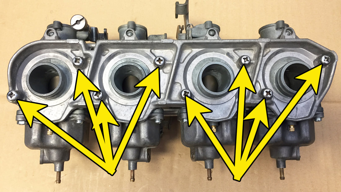
With the throttle slides buttoned up and the choke rod spring in place, you can now put the manifold plate in place. You will find there is one locating pin on the back side of each of the carburetors. These locating pins fit into the top of the manifold plate. It might take a little gentle wiggling around to fit all the pins in, but do not force the pins into place. If things do not fit right, make sure you have the correct fuel rails in the correct places. Yes, that means some disassembly, but you occasionally have to do things over when working with complex carburetors.
Once the manifold plate is in place, secure it with eight Phillips head screws. Once secured, check the throttle and choke for smooth movement. If anything is binding, remove the mounting plate and disassemble as necessary until you find the source of the problem.
The job may look complete, but we still have to put some Blue Loctite on those choke plate screws! If you don’t they could vibrate loose and ruin a cylinder. But before you do that, you should bench test your carbs for leaks. If there is any chance you might have to disassemble the carbs, you don't want Loctite on the screws.
Bench Synchronization and Testing
It is so much easier to do this now than when the carbs are on the bike. I know it’s tempting to go ahead, take a shot and put the carbs on, but if they aren’t dialed in, the performance of the bike will definitely suffer. So let’s get on with bench syncing your carbs. This will only take a few minutes.
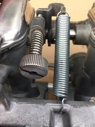
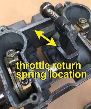
To keep you throttle slides down and in place, you are going to want to first put your throttle return spring back in place (photo right). In case you forgot about this, there is a hook on the throttle stop (attached to the throttle shaft). The spring runs between the hook near throttle stop and a hole between carbs 3 and 4 on the manifold plate (see the picture to the right).
If your spring turns up missing, you can find a replacement at most hardware stores or a Home Depot. Mine was missing, so I took the measurement of the location and found the perfect lightweight spring at Home Depot for less than three bucks. The package had 4 springs in different sizes, so I now have a extra springs from some future project.
I have found that a small drill bit is the perfect tool for adjusting the sync on the carbs. I used a #17 bit, but you can use anything like a 5/32 or 9/64 bit.
As I mentioned before, the slide on the number 2 carb doesn’t have any adjustment feature. That is because you sync all the other carbs to carb 2. Your goal is to have all the other carburetor slides to raise and fall simultaneously with the number 2 slide. If this were not done, one or more cylinders would be running faster or slower than the others creating disharmony and ruining performance.
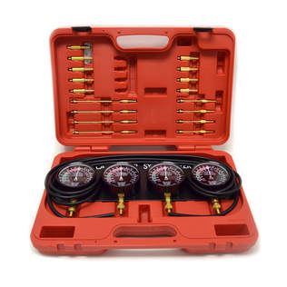 Niche Cycle sells this nice vacuum sync set
With the throttle return spring in place to hold down the slides and small drill bit in hand, first turn the large idle adjustment screw (photo, upper right) until you can just slide your drill bit under the carb two slide. Clockwise will raise the slide, counterclockwise will lower the slide. You want the bit to slide under the slide without raising it or without any noticeable play up and down. Open and close the throttles a couple of times and check the bit again. If you are satisfied that it is a good fit, move over to the carb one slide.
Use the adjustment screw (pictured upper right) to move the slide up and down until you have a good fit. Repeat for slides 3 and 4. Operate the slides with the bell crank a few times then check for fit again. If you need to adjust, repeat the process. Once you are satisfied, place a short screw driver in the adjustment screw slot (do not turn it) to hold the screw in place while you tighten the lock nut. I always check one more time just to make sure I didn’t turn the screw while tightening the nut.
This is the preliminary syncing, which is often good enough for most folks. But, once the carbs are back in place on the bike, you can always sync the carbs with a vacuum device. Niche sells a good one. There are plenty of YouTube videos on syncing your carbs, so we won’t get into that here.
Finally, you’ll want to bench test the carb bank with fuel BEFORE you install it on the bike. I use a little fuel tank off an old mini bike engine. I have an inline petcock installed to cut off and turn on the fuel flow.
If you do this, I highly suggest you run good, ethanol fuel from a spotless test tank, through a quality in-line filter to the fuel spigot on carburetor 2. Make sure the carbs are sitting upright on your work space to emulate the approximate vertical position they would normally be on the bike. You might have to use some little wood blocks to keep the carbs from sitting on the float bowl overflow nipples. Speaking of overflow, I suggest that t you also replace the fuel overflow lines. While you're at it, replace the fuel line as well. With new drain lines connected, you can direct them to a catch can. You'll realize how good an idea this was if one or more of your floats stick.
Okay, with everything set up, turn on the fuel from the test tank. If a carb starts to overflow, give the bowl a light tap or two with a plastic hammer or the butt of a plastic screw driver. Sometimes floats get stuck when they are new or dry. Hopefully all the other parts are installed correctly and you want have to deal with any leaks. But, because the carbs are on the bench, this is so much easier to diagnose and fix than if it was installed on a bike.
If the fuel is coming out of one of the drain tubes, it probably has something to do with the fuel needle not seating correctly. All you have to do is pop off the float bowl and take a look. If it's leaking around the fuel rail, you probably have a damaged O-ring. You'll have to agree, the diagnosis and repair process is a whole lot easier on the bench than trying to do this with the carbs installed on the bike.
If the carbs aren't leaking they you're ready for the last step before installation. With everything done, be sure to put blue Loctite on those screws for on the choke plates. If you don't I absolutely guarantee you, you'll suck one done the intake and ruin your engine. DON'T FORGET!
I hope this tutorial has provided you with some insight into what might seem like a really difficult, scary or even impossible task for some. But like most big projects, if you use the right tools, take your time and follow directions using common sense, a you can not only make this project achievable but have fun doing it.
I'm human and I make mistakes, so if you find something I did wrong, or left out, please let me know and I'll try to correct it.
