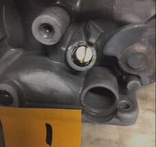
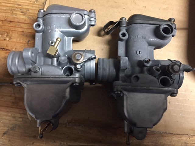
Rebuilding the CB400F and CB350F carburetor set
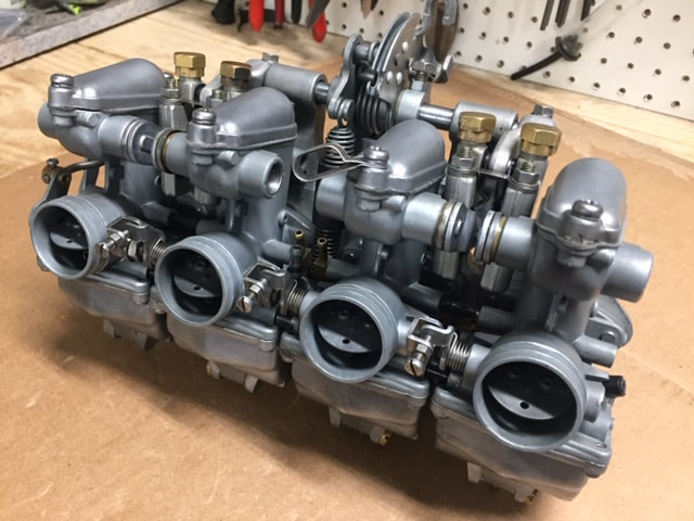
Although I have not yet worked on a CB350F, it is my understanding that this model uses the same Kehin carb as the CB400F with some minor jetting changes. That is why it is included in these instructions. This tutorial covers the step-by-step dismantling, cleaning and reassembly of the carburetor set for these motorcycles.
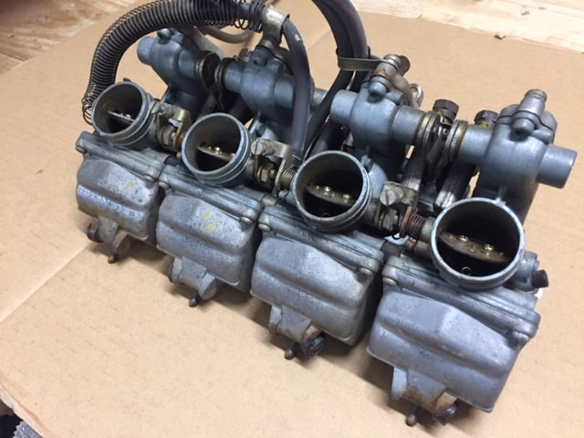
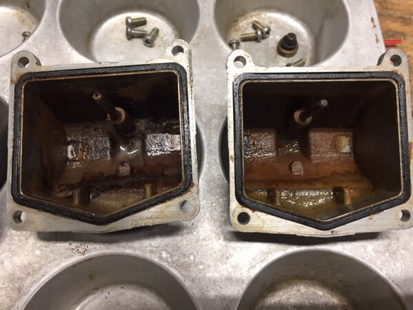
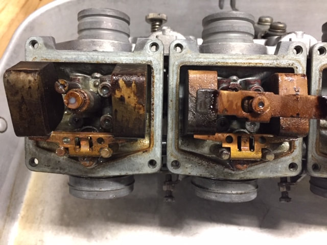
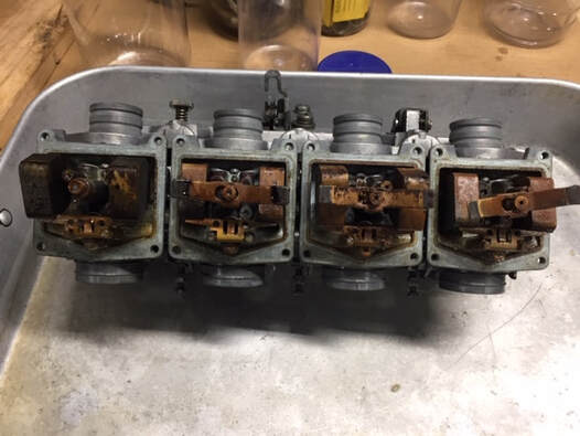 These carbs were really gummed up.
About the Project
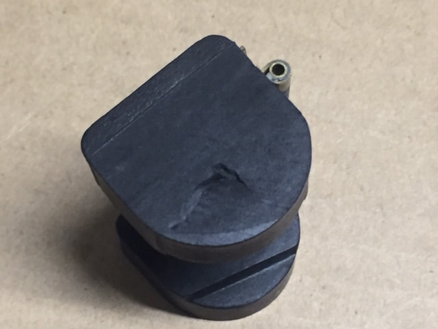
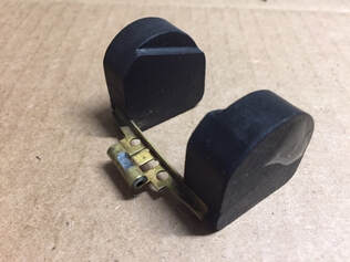
In July of 2020, I was hired to restore a 1976 CB400F. The restoration was still in progress at the time of publication, so for the time being, I have posted a picture of a very similar bike above. Our demonstration bike was purchased by the original owner when he was 16. It has been moved around the country, but always stored in a garage. The bike was amazingly original and complete. When I began the disassembly, I though it was possible no one had ever worked on the bike, including the carbs. That opinion quickly changed when I opened up the carbs for inspection. I immediately noticed the main jet retainer in the number four carb was missing and the float has been punctured by a screw driver. One look at the inside of the carbs and I knew this was not going to be an easy rebuild.
Evaluation:
Before I get started on any carb rebuild, I do a careful evaluation of the condition. From the outside, these carbs looked pretty good. No obvious corrosion or missing parts. It looked like it was running and put away while still running and there weren't any outward signs that an novice mechanic had attempted to work on the carbs.
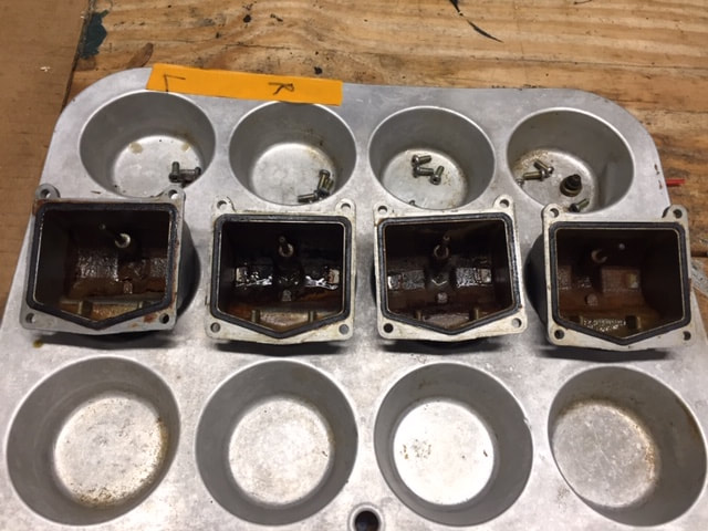
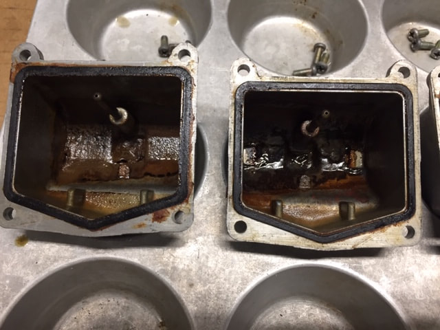
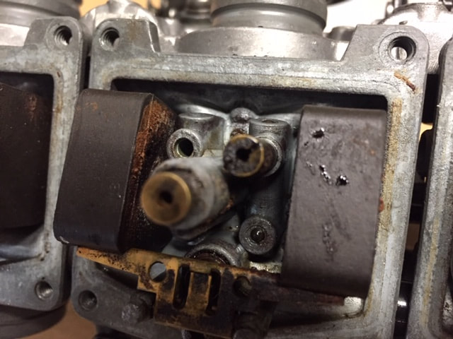
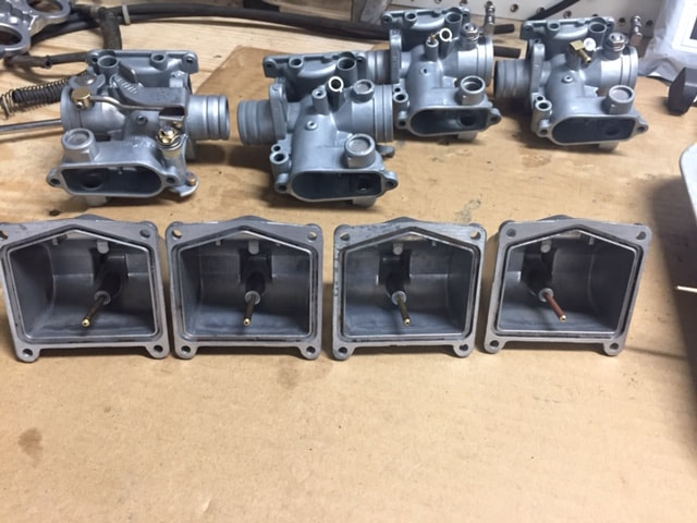
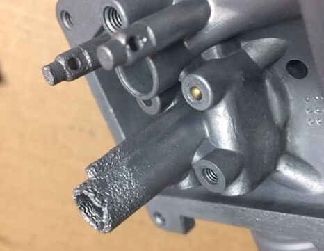
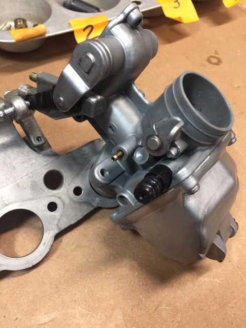
I reached to turn the throttle cable and it was seized. This is not a good sign. It could be a frozen cable, but I could see the cable ends moving, so I knew the issue involved the slides. The photo to the right shows the inside of the carbs. These were horribly gummed up with old, dried gas that had turned into a varnish-like substance (mechanics call this simply varnish - or carb varnish). Every float was seized and would not move up or down. The needle jets, main jet and pilot jet were plugged with varnish. The float bowls were not easy to remove and they were gummed up. Even worse, the top of the jet tower had been submerged in moisture-laden fuel long enough for the fuel to complete evaporate and decompose (at least 10 years). It had heavy corrosion and I didn't know if the carbs were serviceable. Hopefully, your carbs are in better shape. If not, you might try to find a better set on eBay.
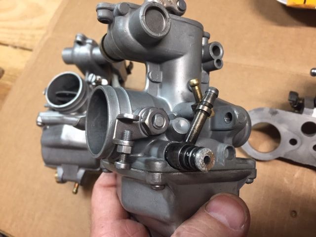
I've posted some close up shots of the carbs below. Not counting bikes there were stored outside for 40 years, flooded underwater, or damaged in a fire, these were some of the worst carbs I've worked on in 50 years. There were close to not making the cut for rebuilding.
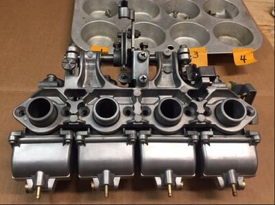
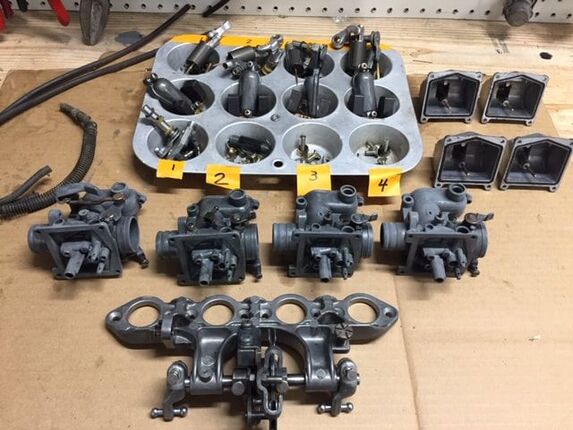
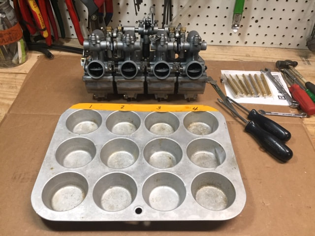
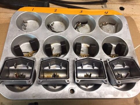 Using a muffin tin like this is the perfect way to easily keep parts sorted
Technical complexity of this project
I've found carburetor rebuilding projects for motorcycles becomes exponentially more difficult the more carbs there are on a bike. Of course, there are carbs that are inherently more difficult than others. Most often, multi-cylinder four-stroke carbs require significantly more skill, then say, a carb off a vintage-two stroke. Some carbs are further complicated by complex linkage arrangements. While more simple carbs are linked together by cable, like the three Mikunis used on a H1 Kawasaki.
The more carbs there are, the easier it is to mix-up parts or lose parts. And unless your methodical in your methods, it's easy to lose track and miss a step - one that could cost you to pull the carbs apart again. For that reason, I would not recommend a project like this for a carburetor novice. Before you tackle a bank of four carbs, it's good to have some experience with a more basic carb like those on a lawn mower, chain saw, single-cylinder motorcycle or even off a vintage automobile.
Rebuilding a set of carbs like these takes a lot of time patience. For the first-time rebuilder, I'd say, set aside at least 20 hours. Don't attempt to do a project like this on Sunday, if you need to ride the bike to work on Monday. You'll end up calling Uber. This project is also not recommended for someone who gives up easily when challenged. These warnings aside, this rebuild can be performed by almost anyone who can read and carefully follow instructions. As long as you have a modicum of mechanical skill and a some basic tools. Even if you don’t have the tools, they are easy to come by and cheap.
Getting prepared for the job
Get prepared for the job before you start. Begin by finding yourself a clean work space. It’s possible you might have to start the project and finish up the next weekend, so organize your parts in such a way they won’t be lost. It’s important to note that to do the job right, you really need to bite the bullet disassemble most of the carb set. It's not as bad as some carbs, because you can leave the choke mechanism in place - unless it is frozen or damaged. Even if you’re very experienced with rebuilding motorcycle carbs, disassembling a bank of carbs for the first time can be a bit daunting. The key to doing the job right is being organized and utilizing a methodical approach.
This guide does not instruct you on removing the carbs from the bike. It’s pretty straight forward and there are posts on you-tube and user groups that can help you with that. Just be sure not to damage or force anything when taking the old carbs off. I use the primary principal of medical ethics for my mechanical work: First, Do No Harm. If you break, damage, or lose parts during disassembly you will end up costing yourself time and money.
When doing a project like this, be sure you label the parts and take plenty of notes. I frequently buy off-brand Ziploc-type bags at Big Lots or discount stores. I get them in gallon and quart sizes. If you label parts (particularly hardware) and put them in a baggie, it makes life much easier when it comes to reassembly. You have to make absolutely sure you do not mix up parts. You have to keep the carb components together with the carb they came off of. This is especially critical with the linkage.
Over the years I’ve found common kitchen products are really handy when rebuilding carbs. A few years ago, I bought a couple of deep aluminum pots with lids for cleaning my parts at a yard sell for $2. I snagged some ice tongs for quarter. I use those for grabbing the parts out of the pots. And, I picked up some old muffin tins for keeping the parts sorted. I think they ran me about 50 cents apiece. Remember I mentioned being organized and methodical at the beginning of this exercise. The muffin pan is particularly helpful when working with multiple carbs. It keeps the parts separate but held together in one place.
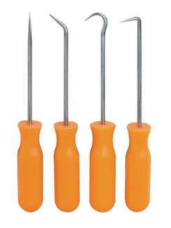
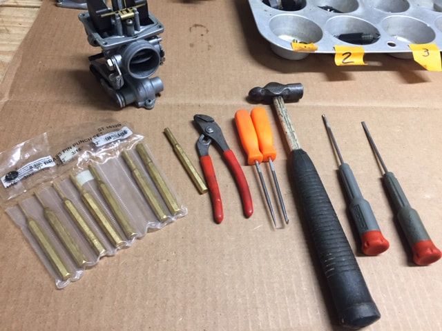
Tools like this inexpensive set are available at Harbor Freight and can be found online
Tools you’ll need
Make it easy on yourself. Use the right tool. If I’m very specific about a tool, it’s because using anything else will eventually cost you time and money. So if I say use an 8mm wrench and you don’t have one, then get one. If you use an adjustable wrench or a vice grip, you’ll ruin the nut or bolt and have to replace it. With tools so available and cheap on Amazon, eBay or from Harbor Freight, it’s just penny wise and pound foolish not to get the right tool.
One of the best tools you can use is a cell phone or digital tablet. I used to draw a lot of diagrams, but these days, I take lots of pictures when I take something apart. It helps me remember how to put things back together. I also use a little spiral-bound notebook and take lots of notes. These notes and pictures have saved me so much time and frustration on projects.
Here is a list of tools and items you will need:
- A #2 flat blade screwdriver
- A new #2, good quality Phillips head screwdriver
- A #3 Phillips head screwdriver
- Small needle nose pliers (4-3/4”)
- Small awl kit (available at Harbor Fright or on-line)
- Small brass drift (punch)
- Small plastic hammer
- Small needle nose vice grips
- 1 gallon of Pine-Sol
- Q-Tips (about 20 or so)
- 7mm, 8mm , 10mm and 13mm combination wrenches
- Small amount of lockwire
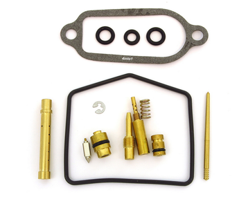 This kit came for 4into1.com. I got five O-rings with my kit.
Parts required for a rebuild:
Rebuild kits are sometimes offered individually, so be sure to get a kit for each carb. I like to have the rebuild kits in hand before I get started on the carbs. Every once in a while, I'll find I need something additional once I get into the carb, but if I don't, I'll have everything I need and won't have to wait for a shipment to finish the rebuild.
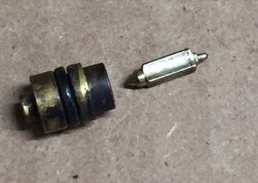
I've found these aftermarket kits, although they're not made by the original manufacturer (Keihin), are usually good quality - although it varies a bit from provider to provider. The jets, jet needles and float needles in the kit I bought for this bike all appeared to be precision made with excellent machining quality. Normally, I use the original jetting from the carbs. With the exception of the float needle and seat, jetting almost never wears out. That's why it can often be reused. With this bike, the jetting was so clogged with resin-like varnish, I decided to give the replacement components a try. I've found the rubber components and gaskets fit well and appear to be as good a quality as the original components. I had some spare O-rings with this kit so I attempted to to stretch them until breaking. They were extremely soft and flexible - just what you want in carburetor O-rings. I also soaked some O-rings in acetone (a really harsh solvent) and they don't breakdown quickly, which is another good sign of quality. I don't know if they are viton O-rings (which are better for harsh fuels) but the originals weren't, so I would say these O-rings are at least as good as the original components. I was surprised to find that a few of the original O-rings on the fuel transfer tubes were still in good shape after 40-plus years!
I don’t have the tools necessary to make microscopic, precision measurements, like one would need to compare jets, but in a visual comparison, the parts look identical to the original components. Over the past several years, I have used aftermarket replacement kits on many types of carbs with good results. But you don't have a lot of choice anyway. Unless you measure and buy your O-rings directly from a supplier, or have a stash of NOS parts (which I'm not sure I would trust the rubber to be good), you won't find many new parts for vintage carbs offered by Honda or Keihin.
Typically, Niche Cycle is a great source for vintage carb kits. They have hundreds of kits, but at this time, do not have a kit for the CB350F or CB450F. So I turned to 4into1.com for this project. Their kit is of comparable in quality to those provided by Niche Cycle and others.
Disassembly
The disassembly of the carbs requires disconnecting the linkage and removing each carb from the manifold bracket. You might ask if it's really necessary to separate the carbs? Sure, it's a lot of extra work and the jets are easily accessible under the float bowl. It could save hours of work - right? Well, not exactly. Yes, you can get to the all the jets, the float needle, and the float bowl gasket by removing the float bowl. Other parts like the drain plug O-ring and the air/fuel mixture screw are easily accessible on the outside of the carb. But, that only address 90 percent of the problem. It's that other 10 percent of the parts that will have you pulling your hair if you don't take the time to replace them. Separating the carbs is the only way to get to the O-rings for the fuel transfer tubes. With age (certainly after 40-plus years) some of these O-rings (if not all will be cracked and dried out. They will certainly be a source for leaks. Even if they didn't leak when you took the carb apart, they'll probably leak when you put them back on, so it's best to address all potential problems at one time. I've also found out what you need to disassemble and what you can leave in place. So, if you follow my instructions, you'll save a lot of time. You also can't get to the jet needle and needle jet without removing the slide, and the slide can't be removed unless you separate the carbs and linkage. So, let's get busy taking this carb apart. It's not as hard as it looks.
The disassembly of the carbs requires disconnecting the linkage and removing each carb from the manifold bracket. You might ask if it's really necessary to separate the carbs? Sure, it's a lot of extra work and the jets are easily accessible under the float bowl. It could save hours of work - right? Well, not exactly. Yes, you can get to the all the jets, the float needle, and the float bowl gasket by removing the float bowl. Other parts like the drain plug O-ring and the air/fuel mixture screw are easily accessible on the outside of the carb. But, that only address 90 percent of the problem. It's that other 10 percent of the parts that will have you pulling your hair if you don't take the time to replace them. Separating the carbs is the only way to get to the O-rings for the fuel transfer tubes. With age (certainly after 40-plus years) some of these O-rings (if not all will be cracked and dried out. They will certainly be a source for leaks. Even if they didn't leak when you took the carb apart, they'll probably leak when you put them back on, so it's best to address all potential problems at one time. I've also found out what you need to disassemble and what you can leave in place. So, if you follow my instructions, you'll save a lot of time. You also can't get to the jet needle and needle jet without removing the slide, and the slide can't be removed unless you separate the carbs and linkage. So, let's get busy taking this carb apart. It's not as hard as it looks.
Identifying the carbs.
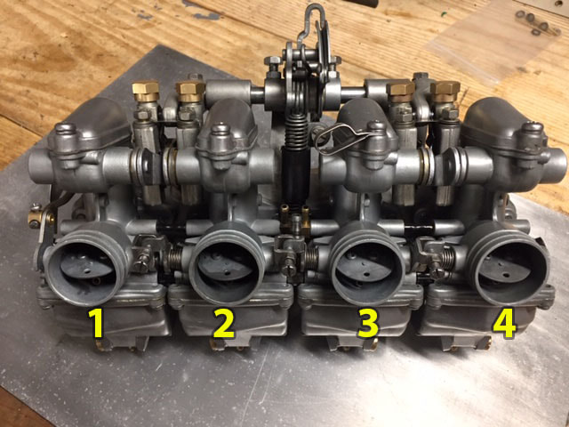
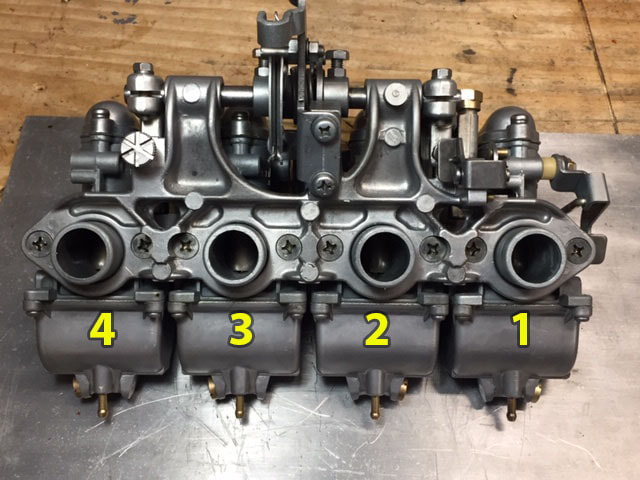
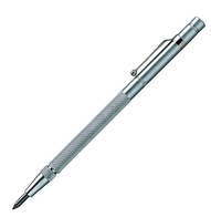
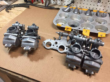
From the back of the carburetor (intake side of carburetor) the number one carb in on the far left side, they are numbered sequentially with the number 4 carb on the far right (see photos below). Make sure you identify the carb with a mark that can't be rubbed away. I like to use a metal scribe and mark the carbs in place where it can't be seen. I marked the bodies as I removed them on the inside of the carb near to where it mounts on the manifold bracket. I also marked the float bowls. This is important, because there are two different float bowls - two have the drain plug pointing to the left, while the other two, have it to the right.
From the back of the carburetor (intake side of carburetor) the number one carb in on the far left side, they are numbered sequentially with the number 4 carb on the far right (see photos below). Make sure you identify the carb with a mark that can't be rubbed away. I like to use a metal scribe and mark the carbs in place where it can't be seen. I marked the bodies as I removed them on the inside of the carb near to where it mounts on the manifold bracket. I also marked the float bowls. This is important, because there are two different float bowls - two have the drain plug pointing to the left, while the other two, have it to the right.
|
Step 1: Use a #2 screw driver to remove the screws from the mixing chamber caps from all carburetors. This is a good place to start separating the parts of each carb.
When working on vintage carbs, it's not unusual to run into screws or nuts that are really difficult to remove. In the colored box below, I've provided some options for removing stuck screws. |
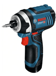
Note: Sometimes you may experience difficulty removing a screw. This is normally a result of corrosion or rust on the screw threads. There a several ways to tackle this, but before I do anything, I usually like to soak the screw with a good penetrating oil like PB Blaster, Aero Kroil, or CRC Knocker Loose. After letting it sit for a few hours, I put a good screwdriver in screw and tap the top of the screw drive with a ball-peen hammer. If that doesn't work, I grab my 12-volt Bosch impact driver and a new driver. That almost always does the trick. I would rarely use it on screws much smaller than 6mm (thread size), but if you have the correct size bit, the hammering action of the driver will usually remove stuck screw fast. An impact driver is not the same as a cordless drill or screw gun. These do not have the hammering action that makes these tools effective.
If you don't want to spend $100 on the Bosch, you can also use an old school impact driver. These are inexpensive. You hit the end of the driver with a small ball-peen hammer to create a similar hammering action as the cordless impact driver - just one blow at a time.
Finally, as a last resort, you can use heat from a small torch to heat the screw and the area of the carb around the screw. BUT, you need to be skilled with a torch before attempting this. There are parts inside the carb that will melt with a little heat. Not to mention you can easily start a FIRE! You could also burn yourself and burn down our shop or house. Never use an open flame around any flammable chemicals. If there is residual gas or resin in the carb, it WILL CATCH ON FIRE! fire. So EXTREME CAUTION MUST BE EXERCISED WITH USING A TORCH and you should never attempt to use one without professional instruction.
If the head of the screw is damaged (stripped), you may want to try a pair of needle-nose Vice Grips clamped around the head of the screw to try to remove the screw.
|
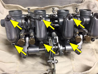
Step 2: Place the carb rack face down. Cushion it under a piece of thick cardboard, a rag or preferably, both. These are larger screw heads than you will normally see on the carb body, so use a #3 Phillips screwdriver to remove the eight screws securing the manifold plate to the carburetors.
If you have an impact driver, place a #3 bit in the driver and you can quickly remove these screws. |
CAUTION: With the manifold plate loose, be extremely careful how you handle the carburetor. With nothing supporting the linkage, it can be easily bent or dislodged before you are prepared to handle it. This could cause you to lose or damage parts that are not easily replaceable.
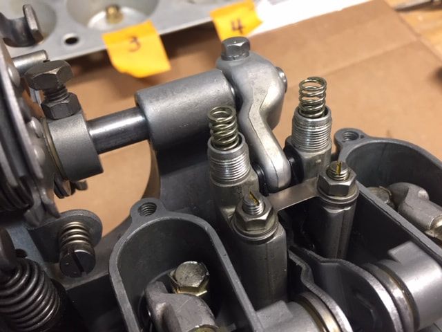
NOTE: The #1 carb has the choke lever attached. Unless frozen, the choke levers can be left in place. Please see information on removing the choke plates at the end of this tutorial.
NOTE: The #1 carb has the choke lever attached. Unless frozen, the choke levers can be left in place. Please see information on removing the choke plates at the end of this tutorial.
|
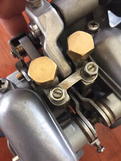
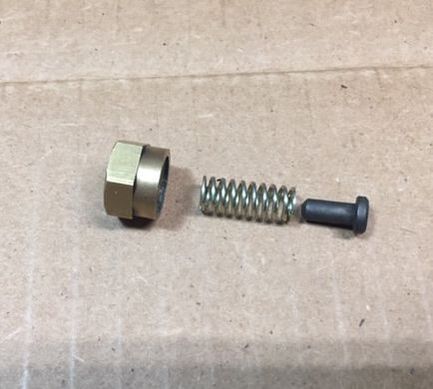
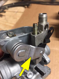
Step 3: Use a 13mm wrench, and carefully remove the bronze cap atop the linkage of the #1 carburetor. CAUTION: Work on one carburetor at a time. Be extremely careful when doing this. Beneath the cap, there is a spring under light pressure and under it, a special black pin with a rounded indention in the head. This pin secures the ball in the linkage. Do not lose this part is will not be easily replaceable. CAUTION: Do not mix parts between carburetors. Keep the parts from each carb segregated from the other carbs. This is especially true of the linkage!
Once you complete this, do the same on the carburetors 2, 3 and 4. Be sure to keep the individual parts of each carburetor separate in their own bins. Helpful Hint: Your cell phone is an excellent way to document your disassembly. |
|
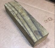
Here's a simple, useful tool you didn't expect to see:
Sure, you can disassemble and reassemble this carb without it, but this little wooden block makes life so much easier. There will be times when you will want to stand up the carbs to work on them. I used this little wooden block and it really helped out - especially with the pictures. The dimensions are 7" x 2" x 1-1/2". It turned out to be perfect but if you have something laying around that's close, it may work too. |
|
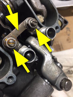
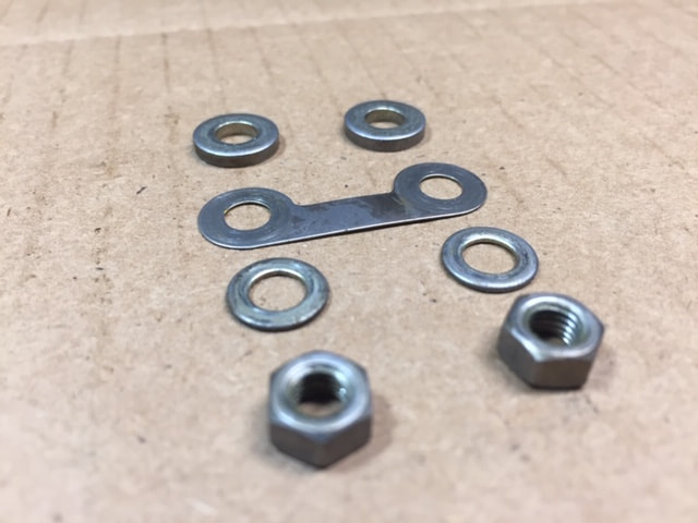
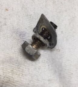
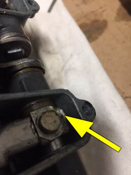
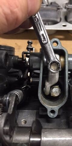
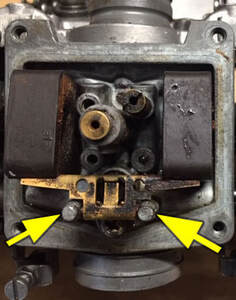
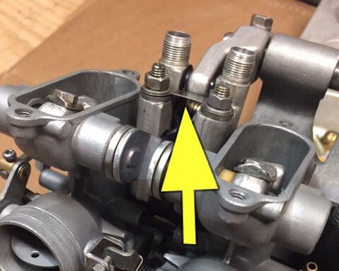
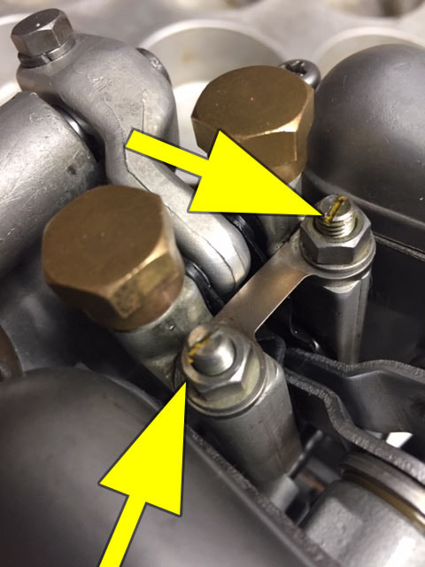
Step 4: On the #1 carb, loosen the two lock nuts on the slide height adjusters attached to the linkage. Remove linking plate and the lock nuts attached to the linkage for the #1 and #2 carb. There is no need to remove or adjust the screws. You may need to use a small screwdriver to keep the screw from turning as you remove the carb. Repeat on carbs 2, 3 and 4.
|
|
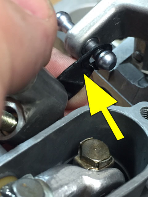
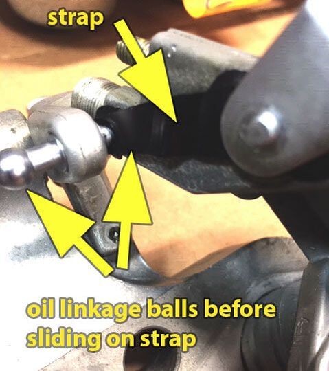
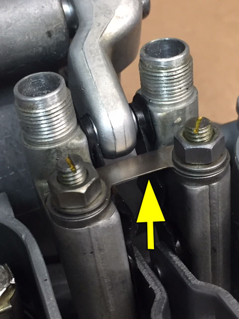
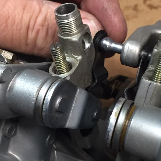
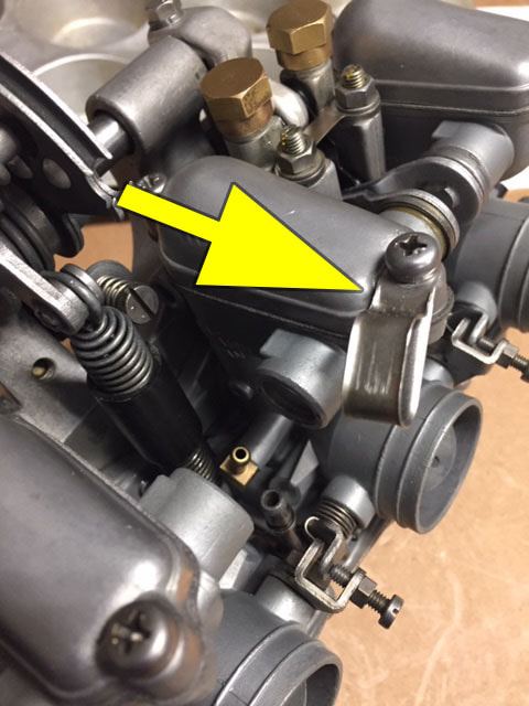
Step 6: Carefully stand the carbs up (sitting on the float bowls), with the intake of the #1 carb facing you. You will notice that the assembly is much more loose now. The only thing holding the carbs together are the linkage, fuel tubes, upper fuel overflow tubes, and thin, rubber security straps. Before you can remove any of the carbs, you must carefully remove these individual rubber security straps or you will break them. You only have to remove the rubber strap at the top where it sits over the linkage ball. The bottom part of the strap stays in place on the linkage (it is not removed). I suggest you first put a little silicone spray or oil on the linkage ball and the rubber strap, then gently slide the strap over the ball. With the strap off, you will be able to remove the carb (see step 7). Rather than attempt to remove all the straps from the linkage balls at the same time, I suggest you remove them individually as you remove the each carbs. In the photo on the right, the rubber strap is being removed from carb #2. Take care not to break these straps as they are not replaceable.
|
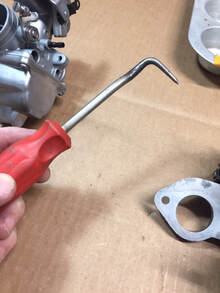
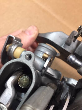
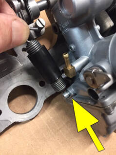
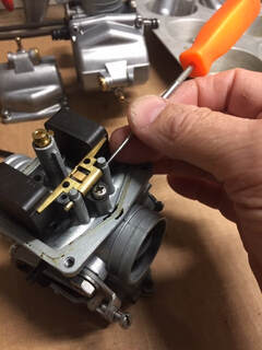
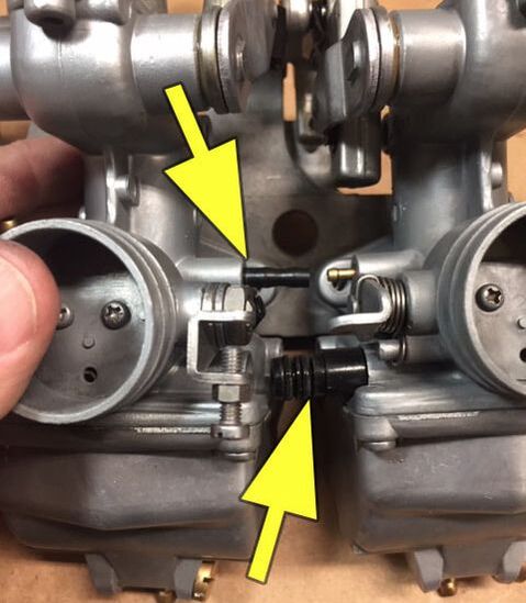
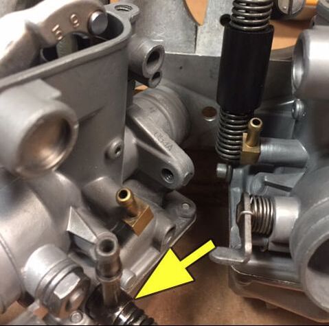
Step 8: If you look between the #2 and #3 carbs, you will see the return spring connects to a small post just above the float bowl on the number 3 carb (see center photo below). This spring will keep you from removing the #2 and #3 carbs. There are a number of tools you can use to remove the spring. I suggest whatever you use, you keep control of the spring.
CAUTION: Removing any spring under pressure is a good way to get hurt. Make sure you have a secure grip on the spring and release it slowly - unloading the pressure before releasing it fully.
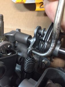
To remove the spring, I used the simple pointed tool in the photo to the right. To remove the spring, lift the spring up and over the nub where it rests on the linkage. After releasing the spring, you can use the instructions in step 6 and 7 to remove the #2 carb. Don't forget to scribe a mark in the #2 carb.
Step 8: With the return spring and #2 carb out of the way, removing the number 3 and 4 carbs will be easy. Remember to first remove the rubber connector (step 6) and follow the procedures outlined in step 7 for separating the carb from the manifold. CAUTION: Do not allow the linkage to slide out and fall from the top of the carburetor. Remember to keep the parts separate - especially the linkage (see step 9). If you don't you will have to do a lot of experimenting (think jigsaw puzzle) to find out which carb and which linkage goes where. Don't forget to scribe identifying numbers in the #3 and #4 carbs.
|
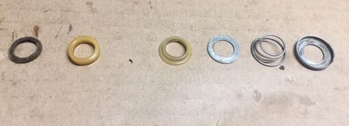
Step 9: With all the carburetors now separated from the manifold plate, you can safely remove the linkage from each carb. Begin with carb #1. Remember, it is critical to keep the correct linkage with the carb it was removed from! With the bolt removed, the shaft should easily slide away from the carb body. Each shaft will have six components which fit over it.
|
|
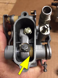
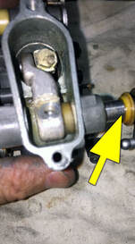
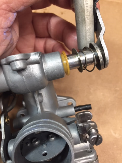
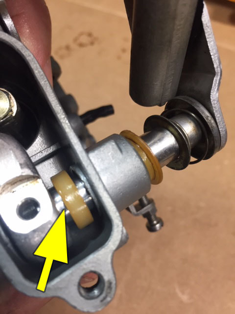
The photo on the right identifies these components. Starting from the left is a felt washer. This sits in a pocket on the side of the carburetor where the shaft is inserted. You may have to remove this with an ice-pick or needle so it isn't lost. The next item is the internal spacer seen in the center and right photo above. Next is the is a spacer with an offset edge.
|
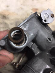 Remove the felt spacer before cleaning, but do not discard.
This spacer sits on the outside edge. After that is a steel flat washer, a spring and a cup for the spring. When removing the shaft from the carb, it is best to put these components back on the shaft and then stored with the components for that particular carb. When finished with carb #1, remove and store the shaft and components from carbs 2 through 4.
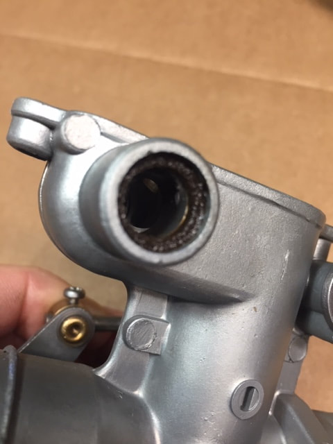
The photo on the right shows the felt washer and the pocket on the side of the carburetor where is sits. The little hooked pick for the set mentioned in step 11 is perfect for this. Do not discard the felt washer. NOS washers are hard to find and I don't know of anyone making replacements at this time. This felt washer will need to be oiled before reinstalling on the carb.
The photo on the right shows the felt washer and the pocket on the side of the carburetor where is sits. The little hooked pick for the set mentioned in step 11 is perfect for this. Do not discard the felt washer. NOS washers are hard to find and I don't know of anyone making replacements at this time. This felt washer will need to be oiled before reinstalling on the carb.
|
Step 10: With the linkage removed from the carbs, you can now begin disassembling the internal components. WORK ON ONE CARB AT A TIME!
Beginning with carb #1, carefully remove the throttle slide. Hopefully, your slides will easily pull out of the carb body. If you find you have a slide stuck inside the carb, I suggest you first soak every access point of the slide with some good penetrating oil like Aero Kroil, PB Blaster or CRC Knocker Lose. Let the oil sit and soak in for several hours. If you're not in a hurry, dab on more oil after a few hours and let it sit overnight. If after a good soaking you find the slides are hesitant to move, try this: Lift the linkage arm that is attached to the slide until it pokes out the top of the carb. Now place a something with a smooth shaft like a large punch or a big #3 Phillips through the hole in the shaft where the linkage shaft was. This way, you can safely pull up on the slide without doing and damage. With the arm out and above the carb, I was able to pull up on the slide about an inch or so. I would spray in a little oil and then carefully tap the slide down. I did this incrementally until the slide released. Unfortunately all of my slides were stuck, so I spent a few hours releasing the slides. If you are careful, you can do this without damaging the slide. Once you've removed slide one, move onto slide 2 through 4. Another reminder, be sure to keep the slide with the carburetor it came from. |
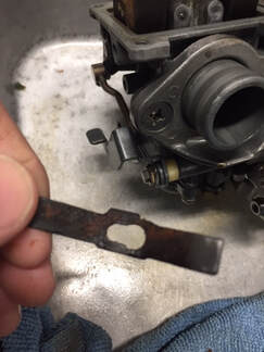 Don't lose this part! It's another of those hard to find parts for this carb.
Step 11: Pick up the #1 carburetor and use a #2 Phillips screw driver to remove the four screws securing the float bowl to the carburetor body. Use a plastic hammer or the plastic butt of your screwdriver to tap around the bowl until it comes off. Do not use a steel hammer as it will damage the bowl. Once the bowl is off, remove the main jet retaining clip (pictured to the right). Remember that the float bowls are different for the left and right side carbs, so keep all parts with the carbs they came off of.
Next, you'll want to remove the pin that keeps the float in place. This is one of those operations where you can very quickly ruin your carburetor - so be extremely careful. Usually, these pins are somewhat loose and can be removed easily - unless they've been gummed up by old gas. When they are tight you need to proceed with caution because you can break off the tower when the pin is inserted and your carb will be ruined.
To get the pin out, it's best to use a very small drift, or small ice pick. Some folks use a sharpened finishing nail, but that doesn't offer much to hold onto. I recommend the small pick that included in the Harbor Freight small pick set. It's perfect for removing float pins. This handy little set only costs about $2 (see picture below). You can buy this set online if you don't have a Harbor Freight store near you. If one or all of your floats are stuck like mine were, that's a pretty good indicator that you may have some trouble getting the pin out. You will first want to spray a little penetrating oil (PB Blaster, Kroil, Mouse Milk or CRC Knock’er Loose) around the pin and float. Give the penetrating oil a couple hours to do its work. Try to get the float loose and moving easily. If you get too aggressive and tap too hard or push too hard on the pin, you’ll break off the float bowl tower. At that point, the carb is ruined. That would be a very expensive mistake – one you want to avoid. So be patient.
If it doesn’t want to come loose, spray it again (generously) and give it a couple more hours to work. After letting the penetrating oil work for a bit longer, try a few more light taps on the the end of the pin. Repeat this until the pin begins to move. I’ve never had one not come out – even when horribly corroded. Once part of the pin protrudes from the other side, You can work it back and forth, using a pair of small needle nose vice grips to grasp the end. Once you get it out, be sure you clean the pin up with a Scotch-Brite pad before reinstalling.
Step 12: With the pin removed, the float will easily lift out. Use extreme care when handling the float. The float is delicate and can be easily damaged. There is also a tab in the middle of the float that is used to adjust the float levels. Be careful not to disturb this tab. If your carbs worked well before the rebuild, then the float tabs are probably still in proper adjustment. You can test your float by placing it in a bowl of water. If, after an hour or so, both sides are floating evenly, you’re in good shape. If one side has dropped, or if you can hear fluid swishing around inside the float, or if you find the float with one or both ends submerged in the bowl, then you’ll need to replace the float.
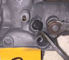
Once you lift out the float, you will have access to the float needle and seat. The needle will usually drop out unless it's gummed up. If it is gummed up, use a small pair of needle nose pliers to grasp the tip of the needle and pull it out. On this carb, Keihin used a removable seat for the float needle. It is held in place by a tiny O-ring located on the outside of the seat. I used a very small set of channel locks (called ignition pliers) to remove this. It doesn't take much force as it is only an O-ring holding the seat in place. You can also use needle nose pliers. Do not let the pliers come into contact with the inside of the seat, especially if you intending on reusing the part.
Once you lift out the float, you will have access to the float needle and seat. The needle will usually drop out unless it's gummed up. If it is gummed up, use a small pair of needle nose pliers to grasp the tip of the needle and pull it out. On this carb, Keihin used a removable seat for the float needle. It is held in place by a tiny O-ring located on the outside of the seat. I used a very small set of channel locks (called ignition pliers) to remove this. It doesn't take much force as it is only an O-ring holding the seat in place. You can also use needle nose pliers. Do not let the pliers come into contact with the inside of the seat, especially if you intending on reusing the part.
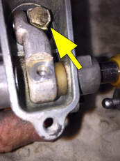 To remove the jet needle, you will need to remove the screw that hold the linkage to the slide as well as a screw.
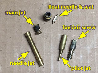
Step 13: With the float, needle jet and seat removed, you can move to the rest of the jets and parts to prepare the carb for cleaning. Besides the needle and seat (step 11), you will need to remove the needle jet, the main jet, the pilot jet and the fuel/air or low speed adjustment screw. If you haven't already removed the gasket from the float blow, you will need to do that as well as the gasket from the carb cap.
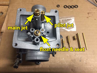
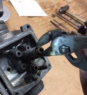
The photo below left shows the location of the main jet, pilot jet as well as the float needle and seat. I used a very small set of channel lock (ignition pliers) to remove the main jet. It should pull right out as it is only held in place by an O-ring. The needle jet should screw out. Use a #1 flat blade screw driver. If you find the screw resists removal, tap on the head lightly with a small brass hammer or ball-peen hammer and then lubricate it with one of the penetrating oils mentioned above. Tap again after oiling and then try again. Make sure your screw driver is a tight fit. If you break off part of the jet, you can use a set of small, needle nose vice grips to remove the jet. If it is still resistant to turning, you may want to try a small pocket torch to heat up the jet and the base around the jet. CAUTION: Be extremely careful when applying an open flame to a carburetor or carburetor component. Please see warning above regarding this.
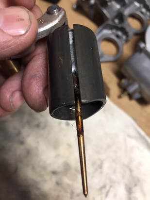
With the main jet removed, you can now remove the needle jet. The main jet sits atop the main jet. It is held in place by the main jet, but sometimes old fuel can make it difficult to remove. I suggest using a small, brass drift or gunsmith punch. You can usually pick up a set of these on eBay for less than $20. The slide is removed from the bottom of the carb! To remove the needle jet, the slide must first removed. This will also remove the jet needle (see step 10). If you look or reach a finger into the center of the carb, you will see the needle jet, protruding just above the base of the carb. Use a 3/16" punch to gently push the jet to the bottom of the carb. One or two taps and it will usually fall out.
Finally, you will need to remove the fuel/air adjustment screw also known as the low speed adjustment screw or pilot range adjustment screw. The screw is located on the side of the carb body. There is a spring under the screw. If you look at the middle picture in the second row below, you will see what appears to be a black screw. This is not really a screw. It is a cap that sits atop the fuel/air adjustment screw. This cap limits adjustment and acts as a fine adjustment device. I will provide more information about this in the assembly section of this tutorial. For reference, you may want to take a picture so you can note the position of the cap later. Use a small pair of pliers and pull the cap straight off. Do no lose or damage this cap as it is not replaceable.
With the cap removed, you can get to the fuel/air screw. This is pictured in the far right photo of the bottom row. When you remove the screw, you will want to first measure, and take note of, the number of turns it takes to close the screw. Do not make the fuel/air screw tight. Only screw until there is light resistance. Screwing the fuel/air adjustment screw in too tight may damage the seat for the screw, which cannot be repaired. Turning clockwise, turn the screw in until stopped. From the factory, this is typically 1-1/4 turns to 1-3/4 turns. Once you know the number of turns required, write it down. Repeat steps 10-13 on carburetors 2, 3 and 4. When you finish this, you will have completed disassembly and will be prepared for cleaning.
NOTE: I am opting to use the original needle jet, so I did not disassemble the top part of the linkage which must be done to remove the slide. If you plan on doing this, you will need to bend the lock tab down on the retaining washer and use a 7mm socket to remove the bolt. With the linkage removed, you can use a #1 Phillips screwdriver to remove the plate that secures the needle jet to the slide. Rather than do all this, I just cleaned the needle in place using a cotton swab and a little acetone.
The cleaning process
Cleaning is a critical stage of rebuilding a carb. If not cleaned completely and correctly, the carb will not work to its fullest potential. I will also introduce a lot of readers to a process unfamiliar to many - vapor blasting.
The problem:
With vintage bikes, the most frequently faced problem is not old grease, dirt or debris - that stuff cleans off relatively easy. The real problem is dried gasoline residue commonly called varnish. As gasoline ages, it changes from a liquid into a sludgy, sticky, horrible-smelling compound that plugs up carbs something awful. The longer gas sits in your carb the worse it gets. The problem is greatly compounded by ethanol in fuels which can start breaking down into varnish in about a year. That is why I run non-ethanol in all my motorcycles and gas-powered equipment. No matter what kind of gas is in the carb, if it's been sitting more than a few years, gas can break down and harden to the point where it will block nearly every circuit and jet in the carb. The more heat and humidity the fuel is exposed to, the worse it gets and the faster it breaks down. If your carbs are really corroded or varnished up, removing any part can be difficult. I’ve had jets snap off as I attempt to take them out.

A lot of folks like to use the purpose-made "carb cleaner" that's sold in most auto parts stores. I don't recommend this type of cleaner for several reasons. When it's fresh (it looses its cleaning strength rapidly), it can damage, discolor and etch the surface of aluminum, brass and steel in just a few hours. If you miss a rubber part, it will be destroyed. Likewise with some plastic parts. I've seen carbs left in cleaner overnight, and the are completely unusable due to damage to the aluminum. Prolonged exposure to the chemicals in carb cleaner can turn aluminum a dark gray or black in just a few hours. Besides the damage it does to the carb, this stuff is highly toxic. Just read the warnings on the can. If it splatters in your eye, it's going to burn you severely, likewise for skin. It's also toxic to plants and wildlife, so there is no safe place to dump it when your done. It's also pricey - between $30 to $30 a gallon depending on where you shop.
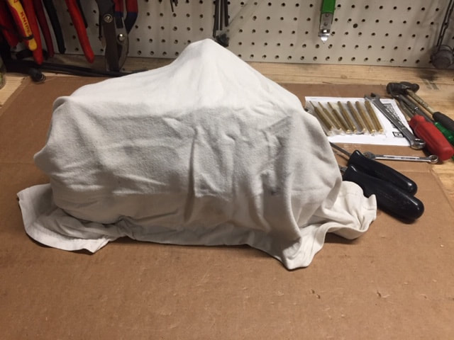
A better choice is Pine-Sol. Yep, that's right, Pine-Sol. The stuff your mom used to clean the bathroom with. It's a lot less expensive and a lot less toxic than purpose-made carb cleaners. You can grab a gallon of Pine-Sol at Target for under $20. That's enough to do a whole bunch of carbs and you'll still have enough left over to clean your house! Pine-Sol works great on ninety percent of the stuff you'll encounter on vintage carbs. Most often I use one part of Pine-Sol to three parts water. If it's tougher stuff, I'll go with 50-50 mix. I've found it also helps if this mixture is heated. You can find cheap hot plates at yard sales or second hand stores. I found a really nice 3-burner hot plate at a local thrift store for less than $10. I bring to mixture to just below boiling and cover it in a large pan. How long you leave the mixture really depends on how bad the varnish is in the carb. Some carbs look great in a few hours, others may take 8-10 hours of soaking. I also recommend leaving this mix outside (covered). Nearly full strength Pine-Sol has an overpowering aroma and can give some folks headaches. I'm sure you don't want kids or pets drinking it either so use with care.
Note: if you soak carbs or any aluminum part in any almost any cleaning chemical for a long enough time, it can change darken the color of the aluminum carb. See note on vapor blasting below.
When it comes to cleaning. Some folks like Simple Green (known to erode aluminum) with others use Pine-Sol or milder grease-cutting detergents. Some folks soak carbs in acetone or gasoline. CAUTION: I do not recommend soaking parts in either gas or acetone as they both are dangerously flammable and are extremely toxic. Please see cautions about open flames, flammable chemicals or toxic chemicals above.
It should be noted that occasionally you may come across carbs that are so bad, they may require stronger stuff. After eight hours of soaking and agitating in hot Pine-Sol , I still had a residual of varnish on these carbs. This is not common. These carbs had the worst varnish I've ever run in to. So I turned to acetone and a small, brass brush to tackle what was left. NOTE: A bronze, brass or plastic bristle brush will not cause sparks and I highly recommend using them when around flammable chemicals. A few words on acetone:
Acetone will also discolor aluminum is a component is soaked in it. Acetone will breakdown rubbers and plastic. Acetone is expensive, usually around $20 a gallon. To fill a container large enough to submerge a carb, you'll use a third to a half of a gallon. And that's the least objective issues.
WARNING: Acetone is very flammable, highly toxic and if you use it in a closed environment, it can cause brain damage or death. If you plan on using acetone, I highly suggest you do so in an open environment (outside), away from any open flames or sparks. I also highly suggest you wear eye and skin protection along with rubber gloves designed to be used with acetone. Read the warning label on the acetone contain before using this chemical. Also, be sure to limit your exposure to no more than a few minutes at a time. Please take note of the additional warnings above on flammable or toxic chemicals.
With that warning out of the way, I used acetone to primarily to clean the float bowls. The resin was so thick it was akin to stripping paint from the bottom of the bowl. I soaked the bowls individually for about 10 minutes in acetone, then scrubbed using a small wire, brass brush and industrial cotton swabs. That did the trick and eventually I was able to remove all the resin residue.
In the picture below, you will see the result of soaking a carb in any cleaner. The one on the left is what I carb looks like in new condition. The one on the right after hours soaking in cleaning chemicals.
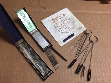 These are some of the tools I use to clean jets and small passageways
Cleaning the small components
Remember the time(s) I when I told you to keep all parts separate for each carb? It comes with a caveat: Once you've inspected and compared the parts, you can gather all the screws, the floats, the jets and the fuel/air screws together for cleaning. They should all be identically sized. But, if you're planning on cleaning the float bowls together, make sure you know what bowl came off what carb. They are different.
So you're probably wondering why I said "compare" in the paragraph above. Well, unless you bought the bike new, you don't know who's worked on the carb. You don't know if someone has replaced the original jetting with something that's not stock or even if the jetting matches from carb to carb. If the jetting doesn't match, it can really drive you crazy. I had a bike many years ago with what looked like original carbs and jets. After chasing down issues for weeks, the bike still popped and backfired like crazy when I backed off the throttle. I was fairly certain the carbs weren't the problem. I was preparing to pull the cylinder head (again) to check the exhaust valves when a buddy, who is a very good mechanic and diagnostician, suggested he have a look at the bike. I was delighted to send it away. He spent several weeks of spare time messing with the bike, testing components and scratching his head. Then, he found the problem and gave me a call. "You'll never believe it," he said laughing. Someone drilled out the needle jet in the right carb." I was floored. I had rebuilt the carbs and the needle jets looked identical. They even stamped the same size stamp and had the factory Keihin star emblem. But, for some reason, someone had substituted the original jet for what appeared to be a custom-made jet, perhaps made for a race bike. Once my buddy replaced the jet, the problem went away. You probably won't run into a problem like that, but it certainly pays to compare all the the jets and other components just to see if they are all stamped the same, not damaged in any way and to check to see if any part stands out because it is different.
When I'm done soaking the jets, I use wires of various sizes to clean the jets. You may notice in the photo, there are have some small file sets that are designed to clean welding tips. These come in handy for opening blocked passages, but I never enlarge the passage with the files. I carefully try to run a the largest wire I can fit though each passage to make sure it is absolutely clear and that all resin is cleaned out. I've found old guitar strings work amazingly well for this. If you have a compressor, it's a great idea to shoot a blast of air through each passage on the carb and through every hole on every jet. Just be sure you have a good hold of the jets. You don't want to lose one by shooting it across the garage (been there, done that). If you don't have a compressor you can buy a can of compressed air on Amazon, at Office Depot or eBay.
Making carbs look new again
There's clean and then is taking the carbs back to factory new condition. This is what most of my restoration clients are looking for. But, I can't blame them, because it's what I expect as well. And the search for this perfection ultimately led me to purchase a Vixen aquaBlast cabinet.
Of course, my primary concern is that the carb is mechanically perfect. But, on a nice restoration project, you want the engine parts to reflect the same care and detail you use with paint work, upholstery or chrome. I've found there is only one way to do this. That is with a wet-blasting technology and the finest media available.
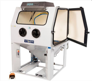 I have a Vixen 1215 blast cabinet in my shop. It brings old aluminum back to a factory new finish.
After years of trying to come up with a safe combination of media and methods to replicate a factory new finish on aluminum engine components, I hit a wall. Dry bead blasting, no matter what media you use, leaves a flat, dull finish. I've had several good dry blast cabinets (bead blasters) for over 40 years. I built my first bead blaster when I was 19. Dry blasting with a course media is great for removing deep rust, corrosion and paint, but you NEVER want to use a dry blaster on ANY internal engine component -especially aluminum - and that includes carburetors. Why? When you dry blast a part, you are using somewhere between 100 to 140 pounds per square inch of air to blast hundreds of thousands of particles (usually rock-hard silicone beads) into the surface of the metal, which is usually soft aluminum. The result is that some of those tiny, hard, silicone beads embed themselves into the metal. At some point, they will let go and start wearing on critical engine parts. It won't take long and they'll join the oil flow to the crankshaft, cams and cylinder walls where the damage can be devastating. I used to thoroughly engine clean parts in mineral spirits with a good water wash and blasting every inch with filtered, high-pressure air. You would think that would remove all beads, but I kept seeing them pop up. Eventually I stopped using dry blasters on internal engine parts. That's because I found you can clean a part that has been dry blasted as much as you want, but you'll never get all the old beads out. In the last ten years or so, this realization has come to many of the best restoration mechanics worldwide. That's why many of them are turning to wet-blasting technology. Wet-blasting uses high-pressure water mixed with the same types of media used in dry blast cabinets. But, because the media is combined with water, shot out of a nozzle at extremely high pressure, it does not allow the media to become embedded on soft metals like aluminum. It is my understanding that this technology originated on Rolls Royce jet engines where wet-blasting is used to hone engine parts.
I bought a wet-blaster (also known as a vapor blaster) a couple of years ago and it's really changed how I clean my parts. I now clean full sets of carb - before disassembling. It does not harm the rubber or plastic components and it allows me to thoroughly inspect the carbs for damage before I start a project. It also alerts me to damaged components like stripped screws -- which might be hidden under years of grime. In the case of these carbs, I vapor blasted the exterior of the carbs, then quickly disassembled them. After soaking the carbs, I vapor blasted the insides of the carbs. This really exposed the erosion of the main jet tower and allowed to confidently make an accurate Go/No Go decision. I also re-blasted the exterior of the carb to get that really nice burnished look of a factory new carb.
For sure, the best way to restore a carb is by having the parts vapor blasted. But, with some WD-40, a soft tooth brush and some Scotch-brite pads, you can remove most of the tinting caused by soaking the parts. The carbs will look pretty good, but it won't return them to a factory new finish. If you can't find someone local who have a vapor blaster, please contact me and I'll give you a quote. This link will take you to the vapor blasting page on my website.
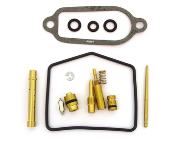 The jet kit I received from 4into1.com had 4 O-rings per carb unlike the kit in this photo
Putting it all back together
With the carb cleaned and all your parts properly sorted, you'll be able to get these carbs back together in a couple hours or so. We'll start by replacing the components in carb #1 and then repeating it on carbs 2 through 4.
On the bottom left photo, you can see kit similar to the kits I purchased from 4into1.com. Unlike the photo, my kits came with 4 larger O-rings for the fuel transfer tubes. The photo on the bottom right shows the location of the components inside the carb.
|
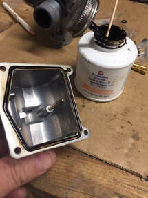
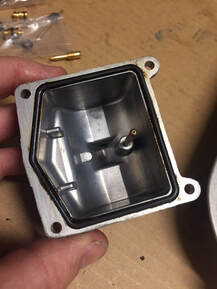
Step 1: A good place to start is with the float bowl. There are just a few easy things you will need to do to get the float bowl ready to install. The first is to install a new float bowl gasket. These types of gaskets don't like to stay where they're put. In the early 80's Keihin began adding little nubs that kept the gasket in place. You won't find them on these float bowls, so I recommend using a gasket sealant to keep the gasket in place.
|
NOTE: If gaskets surfaces are perfectly clean and a new gasket is installed, a gasket sealant is not normally needed unless called for by the manufacturer. These are often used to hold a gasket in place.
I use Permatex Aviation Form-a-Gasket Sealant Liquid. It's sold in most auto parts stores and available on-line as well. I like to use an industrial cotton swab to apply this. These swabs come with extra long wooden shafts which keep your fingers from getting gooey. These swabs are also great for cleaning hard to reach places. I found them on eBay after doing a search for "heavy duty industrial cotton swab." Rather than the fat brush included with the sealant, use a cotton swab to apply a thin layer of sealant into the channel where he gasket sits. Once you have the gasket in place, use a cotton swab and a paper towel moistened with acetone to clean the base of the float bowl. If you don't have any acetone, someone in your household may have some fingernail polish remover. It's normally just acetone.
With that done, you want to put a new O-ring on the brass drain plug for the float bowl. Before the plug is installed, be sure that it is spotlessly clean and that every hole in the plug is open. Run a wire through the holes to be sure they are open. Then blow compressed air though the holes. If you bought your kits individually, each kit should include four larger O-rings for the fuel transfer tubes and 1 smaller O-ring for the float bowl plug. There are only 3 transfer tubes on the carbs, so if you buy four kits, you will end up with four extra larger O-rings. Keep these for spares.
Once you have the smaller O-ring installed on the cleaned drain plug, you can replace the plug in the bottom of the float bowl. Set this bowl aside, and repeat this step on the float bowls for carbs 2-4.
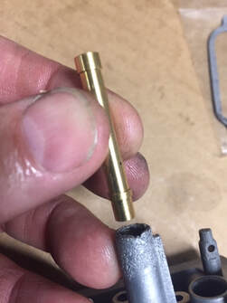 Needle jet being inserted down through the main jet tower on the bottom side of the carb.
Step 2: Before we get going with this step, I like to mention something about jets. Unless you just purchased gaskets and O-rings, your rebuild kits probably came with new needle jets, jet needles, pilot jets, main jets and fuel air screws. If your jets are perfectly clean, with all holes clear, I suggest you use the original Keihin parts. You can tell original Keihin parts by the little star engraved on the components. This is especially true if you bike was known to run well before rebuilding. In my case, the parts were so gummed up with resin, it was much easier to use aftermarket parts. If they work well, I'll be reporting that in the footnotes section of this tutorial. If not, I'll be sure to pass that on as well. The aftermarket parts I purchased did have the same number sizes stamped on them as the factory correct jetting. But, they did not have a Keihin "star" ID, so I they were not made by Keihin. And if they weren't made by Keihin, there is a chance they may not be the exact same size, although marked the same. It will be easy enough to tell once the bike is back on the road.
The first jet we'll replace is the needle jet. This jet works in conjunction with the jet needle which is attached to the bottom of the slide. The jet needle fits inside the needle jet. When the throttle is opened, the is pulled up (via the cable) bringing the jet needle up though the needle jet. This allows more fuel to enter the mixing chamber of the carb.
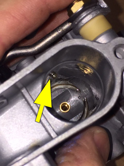
One end of this jet is thinner than the other. The thin side will go in first. When properly in place, about 1/4" of the jet should protrude into the center of the carb.
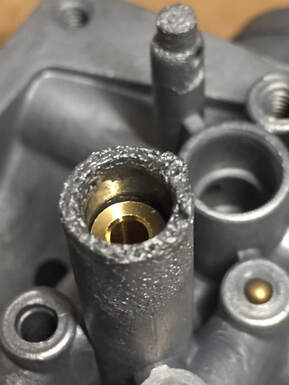
Step 3: With the needle jet in place, you can now install the jet. The main jet sits on top of the needle jet. Before you put the jet in place, spread a fine layer of oil on the surface of the O-ring. That will keep it from tearing or snagging during installation. In this picture below, you can see that I was dealing with a deeply corroded main jet tower. It is questionable whether or not I can get a good seal on the main jet O-ring, but I think enough of the O-ring sits below the corrosion for it to work. I hope so, or my client will have to find a set of carbs without corrosion.
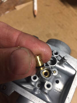
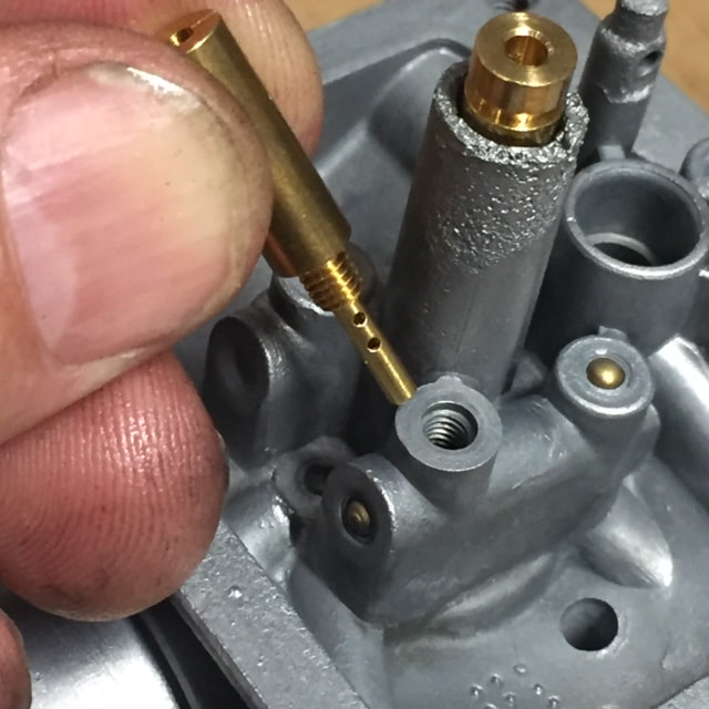
Step 4: Next you'll want to install the pilot jet. This is easy. Just screw it back into the correct place. See photo above right. Anytime you're either loosening or tightening a bronze screw, be careful not to apply too much force. These jets are more fragile than them seem.
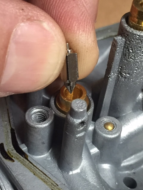
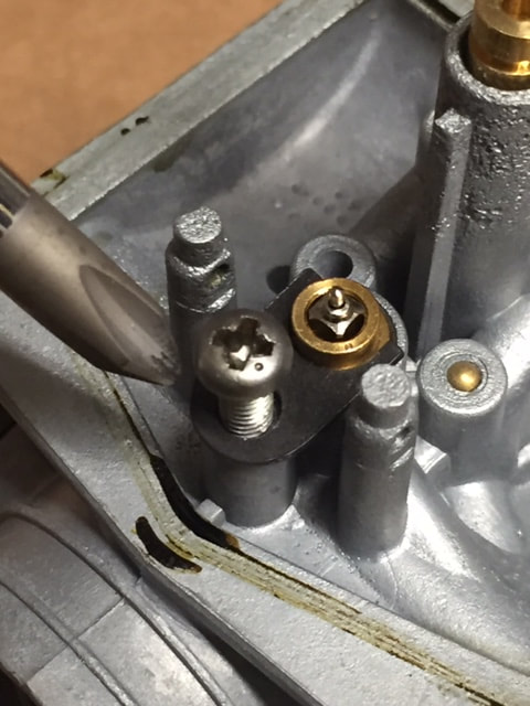
Step 5: After installing the pilot jet, you'll want to install the needle jet seat, the needle jet, the float and float pin. Apply a thin layer of oil to the surface of the O-ring for the float needle seat, then push the seat into place. After that, you can drop the float needle into the seat (left photo). Replace the small, black clip around the seat and secure it by tightening it down using a #2 Phillips screwdriver on the screw. There are five screws that are the same size on this carb - four go to the float bowl. The fifth one is used to secure the float bowl seat clip.
Once you have the float installed, you should consider checking the float height. The factory manual calls for a float height of 21mm. Please take a look at this tutorial I wrote for adjusting Mikuni float heights. In this instance, the float on this Keihin carb is measured the same way: Setting Float Levels on Mikuni Carburetors.
Once you have the float installed, you should consider checking the float height. The factory manual calls for a float height of 21mm. Please take a look at this tutorial I wrote for adjusting Mikuni float heights. In this instance, the float on this Keihin carb is measured the same way: Setting Float Levels on Mikuni Carburetors.
Step 6: Once you have the float in place and the float height checked, you can reinstall the float bowl. Be sure you tighten the screws evenly. In other words, don't tighten one screw all the way, then move to the next. Since there are four screws, use an X-pattern for snugging the screws in place. Start with a top corner and snug up the screw, but do not tighten it. Then move to the opposite corner on the lower side. Sung that screw. Continue on the remaining two screws. Then, using the same pattern, tighten each screw around the float bowl. Using this method is good anytime you're tightening one surface to another. This will keep you from over torquing the surface and warping the metal and it will also help seat the gasket evenly.
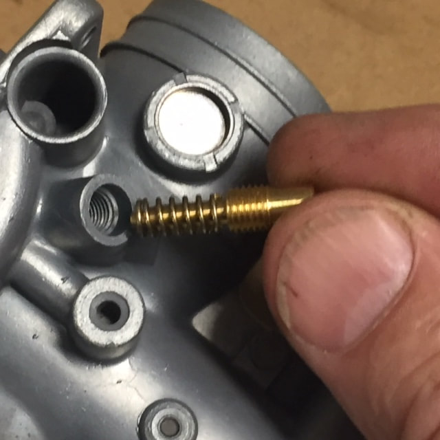
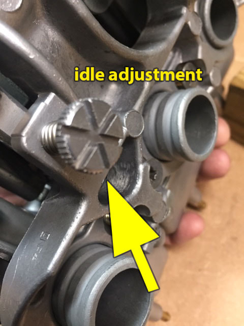
Step 7: During this step, we'll be working with the mixture screw. This little screw adjusts the fuel/air mixture at idle or low speed. It it referred to by a bucket full of names. Among those are the previously mentioned mixture screw; as well as the air-mixture screw; the fuel-mixture screw; the fuel/air mixture screw; the air/fuel mixture screw; the idle-mixture screw and the pilot screw. These various names relate to the function of this screw. The pilot jet meters the fuel (at a fixed rate) at idle speed. This screw woks in conjunction with the pilot jet to adjust the mixture of fuel and at coming into that carb at idle speed - hence the other name, idle-mixture screw or pilot screw. This screw has no effect on the mid-range or top-end mixture settings.
Two of the names refer to the screw's location on the carburetor. If a carburetor has this mixture adjustment screw located closer to the air intake side of the carb (air cleaner side), this will normally be referred to as the air-mixture screw. If the screw is located nearer to the spigot or flange mount side of the carb (nearest to the engine), then it is called a fuel-mixture screw. So to avoid any confusion, we'll just call it the mixture screw.
Before you install the mixture screw, take a look at the notes you took when disassembling the carb. If it took more than 2 two full inward turns to bottom out the screw, it was probably out of adjustment. On most new carbs, I find the factory sets this idle or low speed adjustment screw at 1-1/4 to 1-3/4 turns. And that is what I found on my carbs when I disassembled them. So I would suggest a setting of 1-1/2 turns to begin with. Adjusting these screws is not as easy on a four cylinder motorcycle as it is with single or twin cylinder bike. With those bikes you can adjust the screw by monitoring the RPM. If you'd like to know more about adjusting the pilot jet, that process is fully explained in the chapter Adjusting the Mixture Screw in my article Tuning and Adjusting Mikuni Carbs, on this website. Yes, I realize the article is about Mikuni and these are Keihin, but the principles are the same. To adjust these screws correctly on a four cylinder bike, you'd have to be able to monitor the RPMs of each individual cylinder or you need to have access to an engine air/fuel analyzer or a dynamometer. These are tools most of my readers can't access, so for them, the best alternative is to use the factory settings.
To set the fuel/air screw, first place the spring on the screw and gently turn the screw in clockwise (to the right) until you feel a obvious stop (not just a drag on the screw). As I mentioned before, do not over-tighten or you may damage the seat on the carb. Once stopped, note the position of the line running through the top of the screw head. Using that as a guide, if you turned the screw counterclockwise (backing off the screw) until the mark lined up again, that would be the bottom of the slot, and you would have turned a half turn. Turning to the original starting point would be a full turn. In order not to get confused, you may want to use a Sharpie to put a dot of the side of the screw head where are are beginning your count. That way, every time you come to the dot, it will be a full turn. However you count, you will want to turn the screw out 1-1/2 turns.
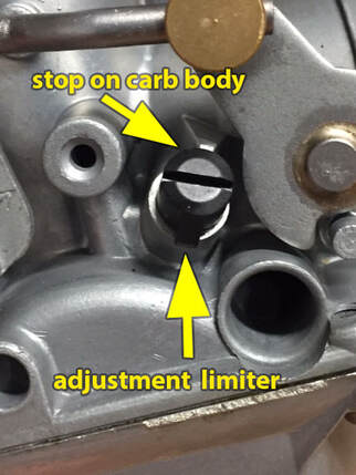
Once you have the mixture screw set correctly, you will need to replace the black plastic cover that acts as an adjustment limiter or a simple fine-tune device. You will notice the screw cap has a tab sticking out from the side. This tab limits the travel of the screw to 1/4 turn in each direction before it hits the stop on the carb. When installing the cap, be sure to place directly in line (180 degrees) from the stop on the carb body as seem the photo on the bottom right.
Step 8: During this step, we'll install the slide, reassemble the throttle linkage to the individual carbs and replace the carb caps. This will complete the assembly of the individual carbs.
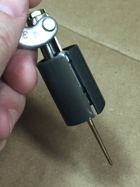
Begin by cleaning the the slide and the jet needle as well as the inside of the the carb where the slide will be placed. Place a very thin layer of machine oil (3-in-1) or clean motor oil on the slide. Note the notch on the side of the slide and the alignment pin on the inside of the carb (photo bottom left). The pin fits inside the notch and keeps the cutaway on the slide facing the intake side of the carburetor (center photo). Push the slide into carb and be sure it moves easily up and down without binding. Next, you'll want to replace the felt washer in the side of the carb. Be sure to add a few drops of oil on the felt. This is the only way the linkage shaft stays lubricated (photo bottom right).
Begin by cleaning the the slide and the jet needle as well as the inside of the the carb where the slide will be placed. Place a very thin layer of machine oil (3-in-1) or clean motor oil on the slide. Note the notch on the side of the slide and the alignment pin on the inside of the carb (photo bottom left). The pin fits inside the notch and keeps the cutaway on the slide facing the intake side of the carburetor (center photo). Push the slide into carb and be sure it moves easily up and down without binding. Next, you'll want to replace the felt washer in the side of the carb. Be sure to add a few drops of oil on the felt. This is the only way the linkage shaft stays lubricated (photo bottom right).
Step 9: Assemble the linkage as seen in the photo below left. Place the spring cup with the lip facing the carb. Then put on the spring with the widest part facing the cup. Next, you put on the flat washer. After that, you'll slide on the external nylon spacer. The widest part sits on top of the flat washer while the narrower part will sit inside the felt washer (see right and center photos below).
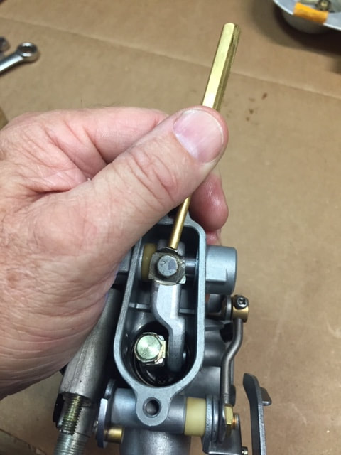
As you are inserting the linkage shaft into the side of the carb, be sure to put the nylon spacer between the side of the carb and the linkage (center photo below). Once you have the shaft inserted through the side of the carb, the nylon spacer and into the linkage, you will need push in on the outside arm, while pushing the linkage connected to the slide over a bit to align the hole in the top of the linkage with the hole in the shaft. Once these two holes line up, insert the small bolt and lock tab into the hole and tighten it with a 7mm socket or wrench. Note: the flat side of the washer should face the linkage. After you tighten the bolt, secure the bolt by bending the lock tab up against the side of the bolt head (bottom right photo).
Do not install the top cap on the carb until you have the carbs mounted together. If there is some reason you have to take it apart to fix something, it's one less part to remove. With this completed on carb #1, repeat assembly steps 2-9 on carbs 2 through 4.
Mounting the carbs to the manifold plate
Step 10: With the individual carbs assembled (for the most part), it's time to link them together. I've always found this to be one of the more difficult steps in working with banked carbs, but on this carb, it was really straightforward and fairly simple.
Start with the #4 carb. Fit the spigot through the manifold plate (left photo below). Leave the carb loose and do not secure with screws. This will be done when all the carbs are in place. Put a little film of oil on the linkage balls where they connect to the carburetor linkages. The oil will allow the rubber security strap and linkage to slide on easily (center photo below). Be really careful not to break the strap when putting it on. No doubt, these straps are dry after sitting on a bike for 40-plus years. You will find that the carb has to be sitting at an angle, a bit off the plate to slide on the security strap and linkage.
Now, make sure the #3 carb has the small, upper fuel overflow line and plastic fuel tube (with four new O-rings) installed on the side of the carb before mounting. Gently push the #4 carb to the right and place the spigot of the #3 carb through the manifold plate. You will need to attach the security strap and linkage for the #3 carb in the same manner as the #4 carb. The next part is a bit tricky the first time you try it, but easy once you get the hang of it. Tilting the carbs away from each other fit the fuel overflow line and fuel tube from the #3 to the #4 carb. Once they're in the right place, very gently push the carbs back together again. This will move the little fuel overflow line onto the bronze fitting on the #4 carb. It will also fit the fuel tube into the fuel extrusion on the carb. It takes a little playing with the carbs to get them to fit together. Be patient and do not force or you'll break or damage these components (see below right photo). In addition to the fuel overflow line and fuel tube being placed together, the choke linkage must also fit together. This is made easy because both choke linkages are spring loaded and unless messed with, will fit right into the other.
Carb confusion? If your linkage or fuel tubes don't match or fit right, you may have mixed up the carbs. I would be a good idea to double check. It's easier to do than you think but the good news is the carbs can be identified easily. On the #4 carb, the fuel tube will be sealed closed on the right side (looking at the choke side of carb). You can test this by trying to blow air in the hole where the fuel tube would go. They look pretty much the same, but on the #4, the right side is sealed. The #4 also has two other identifying features. There is only one fuel overflow fitting on the carb (on the left). Finally, the #4 carb will also have no screw on the choke linkage.
The #1 carb is the easiest to identify. It has the choke operating lever and no fuel overflow line on the left side. Looking at the choke plate on the rear of the carb, the #3 can be identified by the 90 degree fuel overflow fitting on the left side as well as a small nub for mounting the return spring (see below), the #2 will that 90 degree, bronze fitting on the right side. Those fittings will meet together in the center between the two carbs. You can also identify the carbs by looking for those features in the photos below.
The #1 carb is the easiest to identify. It has the choke operating lever and no fuel overflow line on the left side. Looking at the choke plate on the rear of the carb, the #3 can be identified by the 90 degree fuel overflow fitting on the left side as well as a small nub for mounting the return spring (see below), the #2 will that 90 degree, bronze fitting on the right side. Those fittings will meet together in the center between the two carbs. You can also identify the carbs by looking for those features in the photos below.
Step 11: Before you reach for the #2 carb, you want to tie the 3 and 4 carbs together, so nothing slips apart. To do that, replace the thick washer, joining plate, thin washers and nuts (in that order) between the linkage for the 3 and 4 carbs (photo below left).
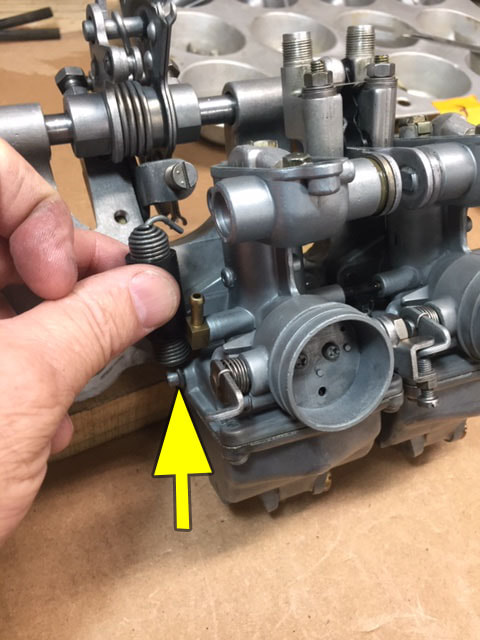
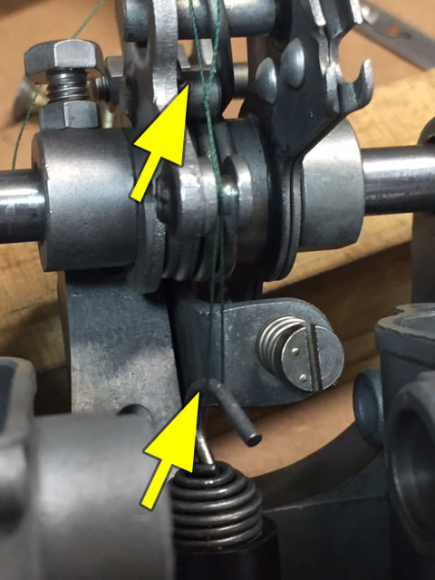
Now, here's one of those tricks you learn with experience. The first time I did this, I skipped this step and had to disassemble everything back to this point. If you're very observant, you noticed the #3 carb has a little nub none of the other carbs have. That nub is where you secure the bottom of the return spring. Here's the trick, if you fit the return spring on that nub before you mount the #2 carb, you won't have to take the carbs apart again! If you didn't see it before, take a close look at the #3 carb. On the left side, just above the float bowl, on the you just mounted you will see a small nub protruding from the left side just above the float bowl near the rear of the carb, there is a tiny nub sticking out (see . This nub is where the bottom of the spring will be attached. You will want to attach the bottom of the spring, but you don't want to attach the top until all the carbs are secure. So, what I did to keep the spring from falling off was to use a piece of heavy duty string to temporarily secure the spring to the linkage. A piece of wire will also work. You just want to keep the string or wire just snug enough to keep the spring from falling off the nub on the bottom carb.
Now, here's one of those tricks you learn with experience. The first time I did this, I skipped this step and had to disassemble everything back to this point. If you're very observant, you noticed the #3 carb has a little nub none of the other carbs have. That nub is where you secure the bottom of the return spring. Here's the trick, if you fit the return spring on that nub before you mount the #2 carb, you won't have to take the carbs apart again! If you didn't see it before, take a close look at the #3 carb. On the left side, just above the float bowl, on the you just mounted you will see a small nub protruding from the left side just above the float bowl near the rear of the carb, there is a tiny nub sticking out (see . This nub is where the bottom of the spring will be attached. You will want to attach the bottom of the spring, but you don't want to attach the top until all the carbs are secure. So, what I did to keep the spring from falling off was to use a piece of heavy duty string to temporarily secure the spring to the linkage. A piece of wire will also work. You just want to keep the string or wire just snug enough to keep the spring from falling off the nub on the bottom carb.
Step 12: Interesting note: with the 3 and 4 carbs mounted, you see that this bank of four carbs is really two pairs of carbs linked together. Not all four cylinder carb sets are like this and it is one of those things that makes this a nice little set of carbs to work on.
To install the #2 carb, you will follow similar steps used for the 3 and 4 carbs. Before you get going though, you will need to install the center fuel tube, which is really a "T" fitting. This tube has an additional tube where the main fuel line comes in from the gas tank and provides fuel for all the carbs. But sure the fuel tube has new O-rings in place.
After installing the central "T" fuel tube on the right side of the carb (looking at the choke plates on the intake side of the carb), place the spigot portion of the carb through the manifold (photo left below). Remember, you will need to attach the rubber security strap and linkage for the #2 carb. Don't forget to put a little oil on the strap and the linkage ball. This will allow the strap to slide on without damage.
Step 13: With carbs 4, 3 and 2 attached, you can now attach carb 1. By now you have experience with the other carbs so it should be getting a little easier. Be sure you put the remaining fuel tube on carb 1. Also make sure you are using fresh O-rings on the fuel tube. Confirm the little overflow tube is in place on the brass fitting coming from the right side of the carb. After you insert the spigot through the manifold plate, you need to fit the security strap and linkage to the ball on throttle linkage. Don't forget to put on a little oil on the ball (center photo above). When fitting this carb in place, the biggest difference is this carb has the master lever for the choke linkages. The screw and nut on the choke arm on this carburetor DO NOT need to be loosened for these parts to fit together (photo above right). Noting that, as you fit the fuel tube and little, fuel overflow line to the #2 carb, you will also need to make sure the choke arm on the #2 carb fits inside the choke arm for the #1 carb. Before you go to the next step, you will also need to replace the little plate that goes between the linkage for carbs 1 and 2. Don't forget the fat washer goes on first and do not tighten the nuts yet (bottom left photo).
Step 14: Stand the carbs up (normal position on bike) and gently push together on both sides to seat the fuel and overflow tubes. Operate the choke lever several times on the #1 carb to be sure all choke plates are moving in unison on all carbs. Inspect the carbs for any part of the above operation that might have been missed. Remember, we still have to connect the return spring, but we'll get to that in a moment.
If everything looks good, you can replace the 8 screws on the back of the manifold plate with a #3 screw driver (center photo below). Draw the screws in sequentially, a little bit at a time. Do not tighten any one screw fully. Once you have all the screws snugged, go back and tighten each screw. After the screws are tight, go back and inspect the carb to make sure all the connections between the carb are straight looking and secure. This is especially true for the fuel tubes.
If everything looks good, you can replace the 8 screws on the back of the manifold plate with a #3 screw driver (center photo below). Draw the screws in sequentially, a little bit at a time. Do not tighten any one screw fully. Once you have all the screws snugged, go back and tighten each screw. After the screws are tight, go back and inspect the carb to make sure all the connections between the carb are straight looking and secure. This is especially true for the fuel tubes.
Step 15: Using a hooked tool, pull the return spring into place. Move the throttle up and down and watch the slides moving to make sure you are getting full motion with all the slides (see photo upper right).
Step 14: At this point, you'll need to reinstall the small cap and spring that puts pressure on to linkage to keep it from sliding out (photo below left). The little black pin will go in first followed by the spring (center photo below). Finally, you'll replace the bronze cap. There is a little pressure from the spring, you be sure you do not cross thread the cap as you are installing. Make sure to screw the first several turns by hand. If the cap resists turning, take it off and correct to position of the cap so it can be screwed down and tightened with a 13mm wrench.
Step 14: At this point, you'll need to reinstall the small cap and spring that puts pressure on to linkage to keep it from sliding out (photo below left). The little black pin will go in first followed by the spring (center photo below). Finally, you'll replace the bronze cap. There is a little pressure from the spring, you be sure you do not cross thread the cap as you are installing. Make sure to screw the first several turns by hand. If the cap resists turning, take it off and correct to position of the cap so it can be screwed down and tightened with a 13mm wrench.
Step 16: If your inspection reveals the carbs to be working correctly and everything in place, you can now install the mixing chamber caps on the carbs. CAUTION: Before you replace the cap, check to make sure all lock tabs have been bent over against the bolt head securing the linkage to the throttle slide. Failure to do this could result in a stuck throttle slide, which could be very dangerous. Also, be sure you have the gasket in place before securing the screws. Note, on the #3 carb, there is a clip to secure the two fuel overflow lines coming off the carbs (see photo below right).
If you've made it this far, you should have no left over parts (other than used components). If so, congratulations, you have completed rebuilding the carbs! Just one more step remains before you install the carbs - bench syncing.
Bench or Static Syncing the Carbs
The final process in our rebuilding journey is bench syncing. This is a critical step that must be completed before the carbs are installed. When that's done, you can vacuum sync if you like, but it may not even be necessary. Please note: If the carbs aren't bench synced if will drastically effect performance of the engine. Imagine four little single-cylinder engines running at the same time. If they aren't in harmony, any one that is not in sync with the others will drag that engine down.
Even if you're counting on vacuum syncing, it's important to bench sync the carbs to get them within range to adjust them with vacuum gauges on the bike.
Step 1: With the throttle spring installed, the throttles aren't just going to easily open and say open. The purpose of the spring is to make sure the throttle closes in the event of a broken cable. The return spring also helps keep the slides pressed up firmly up against the linkage, which is why you want it in place when you're syncing the carb. You don't want any sloppiness that could make your adjustments be inaccurate.
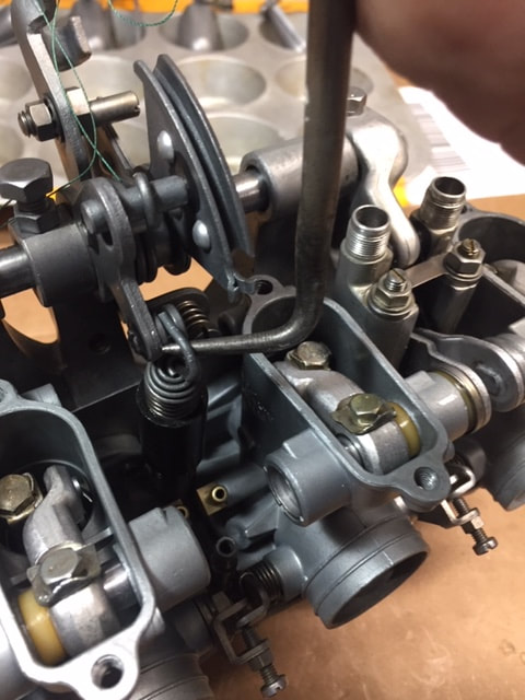
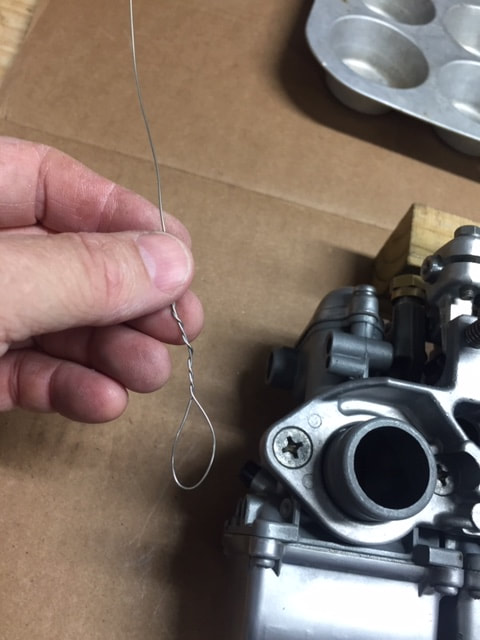
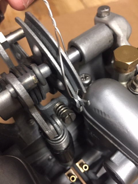
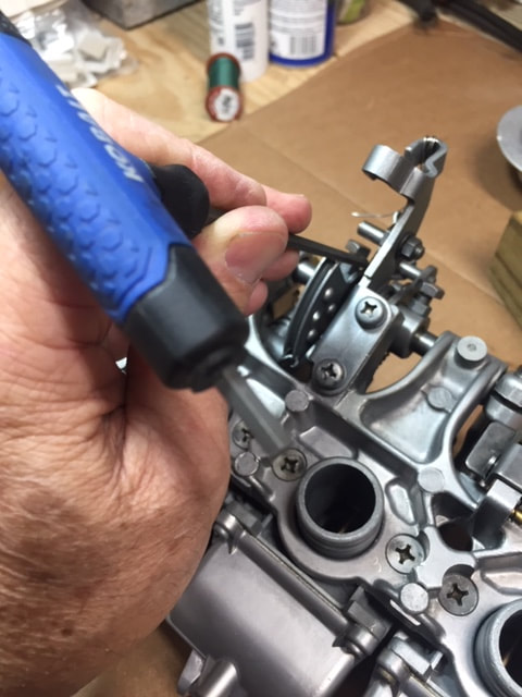
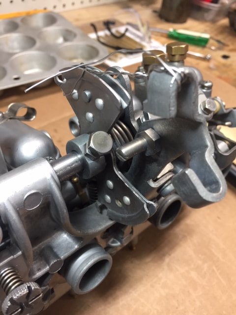
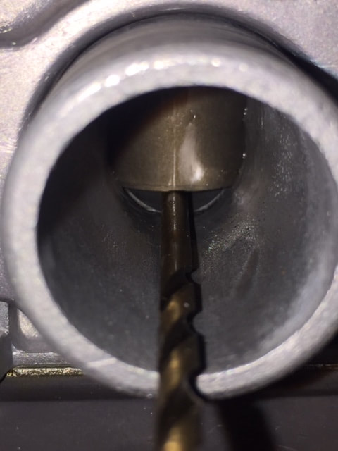
The best way to temporarily hold the throttle open is with a piece of lock wire. Put a loop around one end (see photo below left). Place the loop over the throttle cable guide. You will be pulling the wire towards the spigot (manifold) side of the carb (see center photo below). I found it's best to use a tool of some sort to gain a little leverage over the spring. I used a long, T-handle Allen wrench, but you could also use a long, thin screwdriver or a piece of metal rod. Look closely at where I have the end of the Allen wrench. All I had to do was put just a little pressure on the wrench to open the throttle and hold it in place (bottom right photo). This is much easier than trying to hold onto the wire.
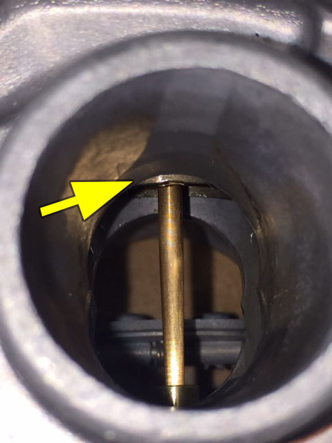
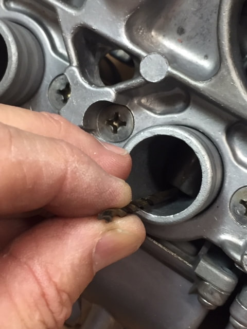
While holding the the throttle open, look down the spigot of the #1 carb and find the position of the throttle slide. Position the slide so you can just barley see it peeking out under the top lip of the spigot (bottom left photo). Now, before the slide moves, wrap the lock wire around the cable bracket to keep it in place. This may take you a couple of attempts to get it right where you want it (center photo below). The #1 carb will be the reference for the other carbs. Simply put, you'll want to adjust the slides on the other carbs to match the position of the #1 carb.
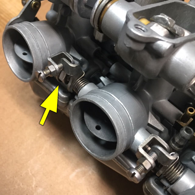
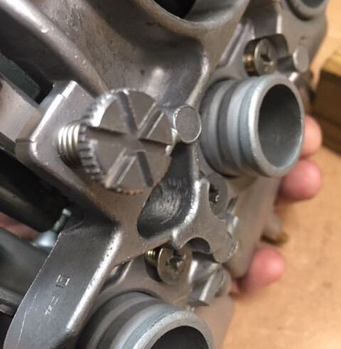
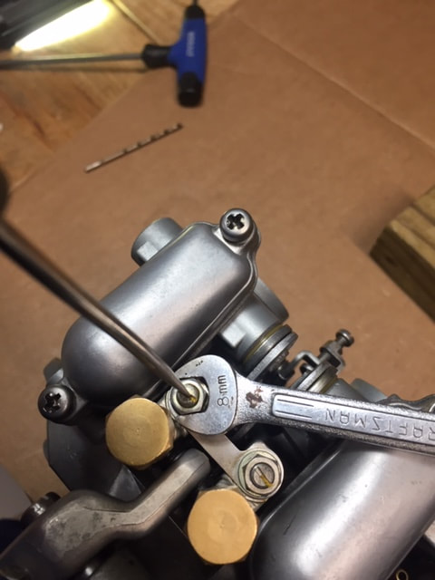
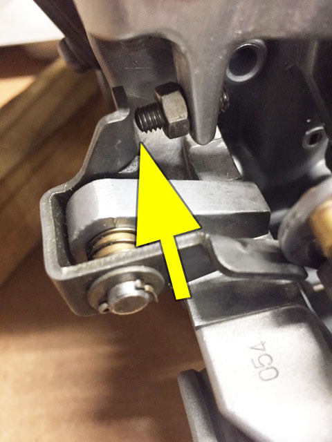
Step 2: While looking at the slide position (height below lip) of the #1 carb, use the adjustment screw to raise or lower the #2 slide to match the position of the #1. Keep in mind, the lock nuts must be loose before you attempt to turn the screw. Turn the screw head clockwise to lower the slide, counterclockwise to raise it (photo below right). Once completed, use the #2 as a guide for the #3 carb. When that's complete, use the #3 as a guide for the #4 carb. You may need to use a bright light to see inside the carbs to get a good look at the slide position. When you're satisfied that all the carbs are close, you may release and remove the lock wire from the linkage. You're close, but not quite finished yet, there are still a couple more steps.
Step 2: While looking at the slide position (height below lip) of the #1 carb, use the adjustment screw to raise or lower the #2 slide to match the position of the #1. Keep in mind, the lock nuts must be loose before you attempt to turn the screw. Turn the screw head clockwise to lower the slide, counterclockwise to raise it (photo below right). Once completed, use the #2 as a guide for the #3 carb. When that's complete, use the #3 as a guide for the #4 carb. You may need to use a bright light to see inside the carbs to get a good look at the slide position. When you're satisfied that all the carbs are close, you may release and remove the lock wire from the linkage. You're close, but not quite finished yet, there are still a couple more steps.
Step 3: With all the slides roughly in the same position, we'll use another simple tool make the adjustment a bit more precise. Screw the idle adjustment screw several turns to raise the height of the throttle slides on all the carbs (photo below left). On my carbs, I found the smooth end of a 1/8th" drill bit to be the perfect tool for fine tune the settings on the slides. But, you could substitute a smooth nail, or metal rod of similar size. If you're unfamiliar with this process, let me explain: we're using the drill bit as a gauge - in the same way someone might use a feeler gauge to measure the gaps between a rocker and a valve.
If you look at the slides, you will see that when you screw in the idle adjustment (left photo below) it raises all the slides at the same time by pushing on the linkage. When you back the screw off, all he slides are lowered at the same time. Start this final adjustment by putting the smooth end of the 1/8" drill bit into the #1 carb (center photo below). If there isn't enough room for the bit to fit under the slide (there should be), turn the idle adjustment screw clockwise to raise the slides. Do this until you can just slide the bit under the slide, and still feel a light drag on the bit (right photo below). If the bit slides in easily without drag, turn the screw counterclockwise and lower the slide a bit. You may need to do this several times until you feel you have it spot on. If there isn't enough adjustment to fit a 1/8" bit under the slide, try using a smaller bit or other tool that will fit.
Once you have the drill bit just barely sliding under the #1 carb slide, try sliding the bit under the #2 carb. This time you will not touch the idle screw! If you find the slide needs to be raised or lowered some to fit, you'll need to make that adjustment with the slide height adjustment screws you turned in Step 2. Once you have #2 dialed in, repeat the process with carbs 2-4. Once you are satisfied with the settings, tighten the nuts on the carbs using an 8mm wrench. Be sure to use a small screwdriver to keep the screw from turning as you tighten the nut (see photo below, second row).
There is one final component I have yet to mention. It is the fast idle device that works in conjunction with the choke lever. As you begin to lift the choke lever, a small arm presses against the throttle linkage raising the RPMs of the bike. This simple, ingenious device is Honda's fast idle for warming up a bike. The idle can be applied while there is almost no choke on, so you won't load up your device. Adjustment is simple, you just want a small amount of clearance between the stop screw and the stop on the linkage (see photo above right). Honda specifies that clearance as 0-0.3mm. Like I said, not a lot.
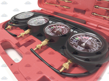
Final notes:
For this motorcycle, I've found in most cases, an accurate bench syncing of the carbs is going to provide as good a result as using a vacuum syncing device. That being said, Honda did recommend vacuum syncing of the carbs in their manual for the bike. To do this, you'll need a carburetor vacuum syncing tool.
Niche Cycle offers a pretty good one made by EMGO. They run a little more than $100 and they're pretty accurate. I've used this set several times with no complaints. You can find this on the Niche Cycle website by following this highlighted link.
If you follow this link, and join the Single Overhead Cam/4 user group (SHOC/4) you will be allowed to download the complete factory manual for the CB450. It has all the technical specs you're looking for including instructions for vacuum syncing the carbs. From the forum log-in page, click on the home page. At the top, you'll see resources and the third item on that list is the manuals and technical information.
A couple more things before I let you go.
Bench test the carbs for leaks:
I would suggest you check the carb for leaks before you install it on the bike. It only takes a couple minutes. Run some new fuel from a clean test tank (through a filter) to the carbs. I use a little fuel tank off an old mini bike engine for this. It works great. I have an in-line filter to clean the fuel and an in-line petcock to start and stop the fuel flow. With my test tank hooked up the the carbs, I let some fuel run into the carbs for a minute or so just to see if the floats are working. If anything leaks, you can quickly turn off the gas at the petcock. It's not that unusual for new float needles to hang up a bit until they have a little fuel run though them. The best way to stop the leak is to tap on the float bowl with a small plastic hammer or the butt of a plastic screwdriver. When you're done, disconnect the test tank and drain the carbs using the drain screws on the bottom of the float bowls.
Use new fuel, a clean tank and a filter
You wouldn't believe how many folks screw up carb rebuilds with contaminated fuel coming from dirty and rusty fuel tanks. First get good, new gas. I highly suggest you run good quality, ethanol-fuel fuel (if you can get it in your area). Transfer the fuel from a spotlessly clean fuel tank. If you are working on a vintage bike that hasn't been started in years, just go ahead and clean the tank. It's well worth your time not to have to rebuild the carbs again. You can use warm Pine-Sol to clean the tank as you did with the carb. Clean the tank several times if you have to. Do this until you no longer see any debris come out when you are rinsing the tank. Then dry out the tank with compressed air. If you don't have a compressor, you can use the blower end of a wet/dry vacuum. After you reinstalled the tank, don't forget to install a new, in-line fuel filter.
Replace all fuel lines, drain lines and fuel overflow tubes
I highly suggest you replace the old fuel and fuel overflow lines. When you putting in that new fuel line, I again suggest you install a new, good-quality, in-line fuel filter. I've seen dirt and debris come out of brand new fuel cans. Besides, those underground fuel tanks at gas stations aren't always spotless containers either. That's way filtering is a must. It only takes a nearly-microscopic amount of dirt to hang up a float needle.
Replace the rubber flange adapters
If possible replace the rubber flange adapters where the spigots of the carbs mount to the cylinder head. On vintage bikes, these are frequently a source of hard-to-find air leaks. It's a lot less frustrating if you replace these old rubber components before you install the carbs.
Well, that's it. I hope this tutorial has provided you with some useful insight into what might seem like a really difficult, scary or even impossible task for some. But like most big projects, if you use the right tools and some common sense, and if you take your time and follow directions, not only is a project like this achievable, you'll have fun doing it.
It takes hours to write and photograph these processes - so much longer than just rebuilding a carb. Unfortunately, I don't have someone who is technically proficient, who is also willing to edit my work for free. So, I expect there will be some mistakes. If you happen to see something that is obviously wrong, please shoot me an email and I'll do my best to address it quickly.
Rick, The Vintage Bike Builder
